
Instruction Manual

Model GD-70D4A-XX Sample Draw Transmitter • 4
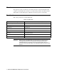
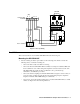
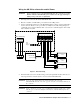
Figure 3: Factory Wiring
Installation
This section describes how to install the GD-70D4A-XX at the monitoring site.
Mounting the GD-70D4A-XX
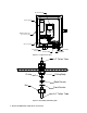
1. Select a mounting site that is representative of the monitoring environment. Consider the
following when you select the mounting site.
• Select a site that is easily accessible for servicing.
• Select a site where the GD-70D4A-XX is not likely to be bumped or disturbed. Make sure
there is sufficient room to make wiring and sample line connections at the bottom of the
GD-70D4A-XX. Also make sure there is sufficient room to perform start-up,
maintenance, and calibration procedures.
• Select a site near the sampling area. The GD-70D4A-XX is designed to detect a variety of
toxic gases many of which are easily absorbed in sample tubing. Keep the sample line
length to a minimum. Teflon PTFE tubing is recommended.
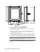
• Use four 1/4” screws through the mounting feet to mount the GD-70D4A-XX to a vertical
surface. See Figure 4 for the mounting dimensions.
FAULT
10987
--++
4-20mADC24V
+V
(AC)
-VLN
BLK
Power Supply
Terminal
654321
GRN
AC in Terminal
GD-70D
Backplate
ALM 1
ALM 2
BLK
GRN
WHT
RED