
Manual


3 How to Operate 3-5. Modes
GD-70D - 34 -
Mode Item LCD Display Details
Regular Maintenance
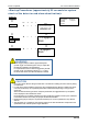
Mode Switching
1-8 M MODE Switch to the regular maintenance mode.
Gas Introduction Display 2-0 GAS TEST Perform the gas introduction test in the regular maintenance mode.
Zero Adjustment 2-1 ZERO Perform the zero adjustment.
Span Adjustment 2-2 SPAN Perform the span adjustment.
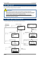
Last Calibrated Date 2-3 LAST CAL Show the last calibrated date.
Bias Voltage (Element
Voltage)
2-4 BIAS
(2-4 E VOLT)
Show the bias voltage.
(Show the element voltage.)
Flow Rate Setting
(adjusted to 0.5 L/min)
2-5 DEF FLOW Set the flow sensor with the flow rate at 0.5 L/min.
Pump Ratio/Flow Rate
Indicator
2-6 FLOW Show the output and flow rate of the current pump.
Detector Temperature 2-7 TEMP Show the current temperature of the installation environment.
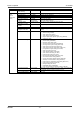
Suggested Warm-up
Completion Date/Time
2-8 WARMTIME Show the suggested warm-up completion for semiconductor type
(SGU).
Environmental Setting 1 2-9 SETTING1 Operation setting
• INHIBIT setting (INHIBIT)
•
Alarm value setting (ALM P)
•
Alarm delay time setting (ALM DLY)
• Regular replacement operation (pump stop) (MAINTE)
•
Fault test (F TEST)
Environmental Setting 2 2-10 SETTING2 Functions setting
•
Address setting (ADDRESS)
• Date/Time setting (DAY TIME)
• Zero suppression value setting (SUPPRESS)
• Zero suppression system setting (SUP TYPE)
• Alarm test time contact setting (TEST RLY)
• Alarm test time external output setting (TEST4-20)
• Energized/De-energized setting (RLY PTRN)
• Alarm type setting (ALM TYP)
• Alarm activation setting (ALM PTRN)
• Alarm value limiter setting (AL LIMIT)
• Fault activation setting (FLT PTRN)
• Flow rate auto-adjustment setting (AT FLOW)
• Zero follower ON/OFF setting (ZERO F)
• 24 hours zero follower ON/OFF setting (ZERO 24F)
• Sensitivity correction ON/OFF setting (S ASSIST)
• External output in maintenance mode setting (MNT OUT)
• External output adjustment (MA 4-20)
• Backlight setting (BK LIGHT)
• ETHERNET setting (ETHERNET)
•
Pump drive level diagnosis ON/OFF setting (PUMP CK)
Pyrolyzer Data Display 2-11 PL DATA When the pyrolyzer unit (PLU-70) is used, a variety of pyrolyzer data
is displayed. (See the operating manual for PLU-70)
Fault Investigation 2-12 FAULT Not used
Maintenance
Mode
(regular
maintenance
mode)
Factory Mode Switching 2-13 F MODE Not used