
Manual

2 Installation 2-3. How to wire
- 23 - GD-70D
2-3. How to wire
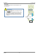
NOTE
To use the pyrolyzer unit (PLU-70), also refer to the individual operating manual.
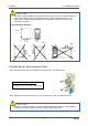
<Recommended Cable>
For 3-wire type 4 - 20 mA
(common power supply)
Shielded cable of CVVS, etc. (1.25sq) - 3-core
For 4-wire type 4 - 20 mA Power: Cable of CVV, etc. (1.25sq) - 2-core
Signal: Shielded cable of CVVS, etc. (1.25sq) - 2-core
For 2-wire type DC power-line
communication system (NT)
Shielded twisted-pair cable of KPEV-S, etc. (1.25sq) - 1P
For contact Cable of CVV, etc. (1.25sq) - max. 6-core
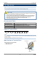
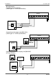
<Figure of Terminal Plate>
1 2 3 4 5 6 7 8 9 10
+ - + -
24VDC 4-20mA ALM1 contact ALM2 contact FAULT contact
NOTE
For the 3-wire type (4 - 20 mA), the terminal 2 is used for common, and the terminals 2(-) and 3(+) are used
to output 4 - 20 mA.
For the NT specification, the terminals 3 and 4 are not used.
<Specifications of Terminal Plate>
Specifications of terminal plate
• Rated voltage: 250 VDC
• Rated current: 16 A
CAUTION
• Be careful not to damage the internal electronic circuit when wiring. In addition, be careful not to apply
stresses on the detector when (overweight) cables are installed.
• The power cables and signal cables must not be installed together with the motor power cables, etc.
When these cables must be installed together for unavoidable reasons, put the power cables and
signal cables in a metal conduit. The conduit must be connected to a grounding circuit.
• When stranded wires are used, prevent wires from contacting each other.
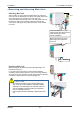
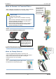
• Use the dedicated handling lever to wire.
Wiring hole
Driver slot
Conductive
part
Cage
clamp/spring
Top handling slot