
Manual


1 Overview 1-4. Names and functions for each part
GD-70D - 10 -
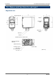
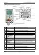
<Front Panel and Character LCD>
①
MODE key
Used to enter the maintenance mode.
It is also used to cancel or skip in a specific mode.
②
TEST/SET key
Used to enter the test mode.
It is used for value confirmation and so on in a specific mode.
③
▲ key
Used to switch screen or change a value (UP).
④
▼ key
Used to switch screen or change a value (DOWN).
⑤
Lock lever
Lever to lock the main unit. Push it to attach or detach the main unit.
⑥
Sensor unit nameplate
display window
Window to look at the nameplate of the sensor unit.
You can identify the currently attached sensor unit.
⑦
Power lamp (POWER)
Power lamp. It lights in green when the power is on.
⑧
First alarm lamp
(ALM1)
First alarm lamp. It lights in red when the first alarm is reached.
⑨
Second alarm lamp
(ALM2)
Second alarm lamp. It lights in red when the second alarm is reached.
⑩
Fault lamp (FAULT)
Fault lamp. It lights in yellow when an abnormality is detected in the detector.
⑪
Gas name display
Displays the gas name in chemical formula and so on (e.g. Silane = SIH4).
⑫
Concentration value
display
Displays the gas concentration and so on.
⑬
Unit display
Displays the unit according to the specification (ppm, ppb, vol%, %, %LEL).
⑭
Concentration bar
indicator
The detectable range (full scale = FS) is divided into 20 with bars. The
increase in concentration is displayed in proportion to the full scale.
⑮
Alarm setpoint
indicator
The alarm setpoints (AL1 and AL2) are indicated on the concentration bar.
⑯
Flow rate indicator
Displays the suction flow rate. The center of the bars means the normal
suction flow rate of 0.5 L/min.
⑰
Communication
indicator
For GD-70D-NT, this indicator is displayed while transmitting data with the
upper unit (TX, RX).
⑱
Maintenance indicator
Displayed during the maintenance mode. When this indicator is displayed,
the alarm contact is disconnected to be disabled.
⑲
Inhibit indicator
Displayed when the inhibition (point skip) is set.
⑳
Pyrolyzer unit
connection indicator
Displayed when the dedicated pyrolyzer unit (PLU-70) is connected.
c MODE key
d TEST/SET key
e ▲key
f ▼key
gLock lever
hSensor unit nameplate display window
iPower lamp
jFirst alarm lamp
kSecond alarm lamp
lFault lamp
⑪Gas name display
⑫Concentration
value displa
y
⑬Unit display
⑭Concentration
bar indicator
⑮Alarm setpoint
indicator
⑯Flow rate
indicator
⑰Communication
indicator
⑱Maintenance
indicator
⑲Inhibit indicator
⑳Pyrolyzer unit
connection indicator