Gas Detector Head GD-70D Series Operating Manual Request for the Customers • Read and understand this operating manual before using the detector. • You must operate the detector in accordance with the operating manual. • Regardless of warranty period, we shall not make any compensation for accidents and damage caused by using this product. The compensation shall be made only under the warranty policy of products or parts replacement.
Preface Preface Thank you for choosing our gas detector head GD-70D Series. Please verify that the model number of the product you purchased is included in the specifications on this manual. This manual explains how to use the detector and its specifications. It contains information required for using the detector properly.
Preface .................................................................................................................... 2 Important Notices on Safety .................................................................................... 4 1 1-1. 1-2. 1-3. 1-4. 1-5. 1-6. Overview ................................................................................................................. Product Components.................................................................................
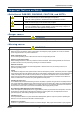
Important Notices on Safety Important Notices on Safety DANGER WARNING CAUTION NOTE Indicates an imminently hazardous situation which, if not avoided, will result in death or serious injury or serious damage to the product. The use of this symbol is to be limited to the most extreme situation. Indicates a potentially hazardous situation which, if not avoided, could result in death or serious injury on the human body or object.
Important Notices on Safety CAUTION Do not use a transceiver (walkie-talkie) near the detector. Radio wave from a transceiver near the detector or its cables may disturb commands. when using a transceiver, it must be used in a place where it disturbs nothing. To restart the detector, you must wait five seconds more before doing it. Restarting the detector within five seconds may cause errors.
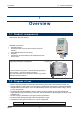
1 Overview 1-1. Product components 1 Overview 1-1. Product components • Operating manual • Protective rubber cap (to be removed when using the detector) • Dedicated handling lever (for wiring) • Dust filter • Interference gas removal filter (to be supplied with some sensor units) Pyrolyzer unit * This is needed in "pyrolyzer + electrochemical type (ESU)" and "pyrolyzer + pyrolysis-particle type (SSU)".
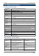
1 Overview 1-3. Product specifications 1-3. Product specifications Concentration Display Suction Flow Rate Power Display Displays Gas Alarm Display Gas Alarm Activation Gas Alarm Contact Fault Alarm/Self Diagnosis Fault Alarm Display Fault Alarm Activation Fault Alarm Contact Contact Capacity Recommended Contact Cable Functions Tube Connecting Hole Initial Clear Structure External Dimensions Weight Outer Color Character LCD (Digital and Bar Meter Display) 0.
1 Overview 1-3.
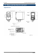
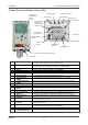
1 Overview 1-4. Names and functions for each part 1-4.
1 Overview 1-4.
1 Overview 1-5. Units description 1-5. Units description The detector consists of the following units. Pump unit Wall-mounted unit Main unit Sensor unit CAUTION • Each unit consists of precision parts. When a unit is detached, be careful not to drop it. Dropping the unit compromises its original performance or causes malfunctions. 1. Push the two buttons at the top of the main unit together to open the front cover.
1 Overview 1-5. Units description A sensor unit installed in the detector is the same regardless of the detection principle, thus sensor units are interchangeable. Each sensor unit has a different color in accordance with the principle as shown below. How to handle the sensor unit is varies depending on its principle. CAUTION • The sensor unit must be handled carefully to ensure quality as safety device.
1 Overview 1-5. Units description Semiconductor type (SGU) • • Before using the sensor unit, it needs to be warmed up for a specified time. The sensor unit is warmed up sufficiently in our factory before it is delivered to you. Therefore, after you receive the sensor unit, please use it as soon as possible so that unpowered time is minimized. The warm-up (powered) time before using the sensor unit is related to the unpowered time.
1 Overview 1-6. Block diagram Mounting hole: A hole for wall-mount. Terminal plate: A terminal to which a power supply, signal cables and other external wires are connected (10P). Lock lever: A lever to lock the main unit. 1-6.
1 Overview 1-6.
2 Installation 2-1. Requirements 2 Installation 2-1. Requirements Not only the first-time users but also the users who have already used the product must follow the operating precautions. Ignoring the precautions may damage the detector, resulting in inaccurate gas detection. CAUTION • After you received the detector, start using the detector within the specified operation start limit of the sensor unit. CAUTION • This is a precision instrument.
2 Installation 2-1. Requirements Do not install the detector in a place exposed to direct sunlight or sudden changes in the temperature. When you select installation sites, avoid a place where it is exposed to direct sunlight or radiant heat (infrared rays emitted from a high-temperature object), and where the temperature changes suddenly. Condensation may be formed inside the detector, or the detector cannot adjust to sudden changes in the temperature.
2 Installation 2-1. Requirements Introducing protective measures against lightning If cables are installed outside the factory/plant, or if internal cables are installed in the same duct as the cables coming from outside the factory/plant, "lightning" will cause problems. Because lightning acts as a large emission source while cables act as a receiving antenna, devices connected to the cables may be damaged. Lightning cannot be prevented.
2 Installation 2-2. Installation of detector GD-70D SK2 Power supply Load Coil SK1 Power supply Alarm contact External relay (low voltage relay) * SK1, SK2: Surge absorbing parts 2-2. Installation of detector NOTE To use the pyrolyzer unit (PLU-70), also refer to the individual operating manual. CAUTION • Before installing the detector, remove the protective rubber caps from GAS IN and GAS OUT.
2 Installation 2-2. Installation of detector (90) Leave the diagonal line area so that the installation space is reserved. (300) (30) (150) When installing by using 2 screws Maintenance space Maintenance space When installing by using 3 screws Maintenance space Maintenance space Maintenance space (Unit: mm) Maintenance space CAUTION • It is recommended that installation points should be away from each other for 10 mm or more.
2 Installation 2-2. Installation of detector CAUTION • The detector must be installed in the right direction to ensure its performance. Install the detector as shown on the following example, and adjust its position so that it is placed horizontally. (* The direction of the detector must also be kept during transportation, including when it is removed temporarily or relocated.
2 Installation 2-2. Installation of detector Attaching Main Unit At the position of 10 mm above the wall hanger unit, press the main unit onto the wall hanger unit. Be sure to fit both side hooks of the wall hanger unit in the grooves of the main unit. Then press down the main unit to fix it. The lock at the bottom of the main unit clicks to fix it properly. Make sure that the top center of the wall hanger unit is above the main unit as viewed from front.
2 Installation 2-3. How to wire 2-3. How to wire NOTE To use the pyrolyzer unit (PLU-70), also refer to the individual operating manual. CAUTION • Be careful not to damage the internal electronic circuit when wiring. In addition, be careful not to apply stresses on the detector when (overweight) cables are installed. • The power cables and signal cables must not be installed together with the motor power cables, etc.
2 Installation 2-3. How to wire Connection conditions • • • Cable: 0.08 - 2.5mm2 Bare wire length: 8 - 9 mm Connecting tool: Dedicated handling lever (accessory) Dedicated handling lever CAUTION • The specified bare wire length must be observed when the wire insulation is peeled off. • Improper clamping of the wire due to a shorter bare wire length may cause defective electrification or heating.
2 Installation 2-3. How to wire When cables are connected to the connectors, use the dedicated lever or a flathead screwdriver to do it as shown below. Push the dedicated handling lever to open the terminals, into which you can insert wires (one wire to one terminal). CAUTION • The right tools must be used. • In principal, one wire can be connected to one wiring hole. • When the wire is inserted into the driver slot by mistake, it does not contact the conductive part.
2 Installation 2-3. How to wire Grounding Use the grounding terminal to connect the detector to your grounding circuit. WARNING • Before turning on the detector, do not forget to connect it to a grounding circuit. • For stable operation of the detector and safety , it must be connected to a grounding circuit. Do not connect the grounding wire to a gas pipe. The grounding must be made as D type grounding (below 100 Ω of grounding resistance).
2 Installation 2-3. How to wire Wiring Example Connecting to the indicator (3-wire type - 4 - 20 mA specification) GD-70D 1 2 3 4 5 6 7 8 9 10 RM-593, etc.
2 Installation 2-3. How to wire NOTE To use the pyrolyzer unit (PLU-70), also refer to the individual operating manual. The detector has a Rc1/4 thread inside of the sampling inlet/outlet (GAS IN, GAS OUT), to which "polypropylene" unions are normally attached. Because their material is varies depending on the gas to be used, please specify the gas. The compatible tube is a Teflon tube of φ6 (OD) - φ4 (ID).
2 Installation 2-4. Relocate 2-4. Relocate When the detector is relocated, select a new place in accordance with "Precautions for installation site" and "2-2. How to install". For information on wiring and tubing, see "2-3. How to wire" and "How to tube". The unpowered time must be minimized when the detector is relocated. CAUTION • When you use a relocated or stopped/stored detector again, do not forget to perform a gas calibration.
3 How to Operate 3-1. Preparation for start-up 3 How to Operate 3-1. Preparation for start-up Before connecting a power supply, read and understand the following precautions. Ignoring these precautions may cause an electric shock or damage the detector. • Connect the detector to a grounding circuit. • Check whether the wiring is connected to external circuit properly. • Check whether the power supply voltage is compliant with the specification.
3 How to Operate 3-2. How to start the detector Power On ↓ Initial Clear PW A1 A2 ● ○ ○ LCD F ○ PW:POWER A1:ALM1 A2:ALM2 F:FAULT ●:Lamp on ○:Lamp off ────── WARM UP ↓ Gas Specifications Display ● ○ ○ ○ SIH4 ↓ Detection Mode ↓ 15.0ppm ● ○ ○ ○ ↓ 0.0ppm SIH4 WARNING • When Oxygen (OSU) is selected, approximately AIR (normal oxygen concentration) (20.
3 How to Operate 3-3. How to exit 3-3. How to exit To turn off the detector, open the switch cover on the bottom of the main unit, and turn "OFF" the power switch. Then, turn off the power supply (24 VDC) to the detector. WARNING • When the detector is turned off, an alarm may be activated on the upper (central) system. Before turning off the detector, the inhibit (point skip) on the upper (central) system must be activated.
3 How to Operate 3-5. Modes WARNING • When the detector enters each mode from the detection mode while an alarm is activated, the alarm contact is released. Flow Rate Indicator Because the suction flow rate of the detector is automatically adjusted by the flow rate control function, the flow rate, in principal, does not need to be controlled. As shown on the figure below, when the flow rate does not correspond to the specified flow rate for some reasons, it is adjusted automatically.
3 How to Operate Mode Maintenance Mode (regular maintenance mode) GD-70D 3-5. Modes Item Regular Maintenance Mode Switching Gas Introduction Display Zero Adjustment Span Adjustment Last Calibrated Date Bias Voltage (Element Voltage) Flow Rate Setting (adjusted to 0.5 L/min) Pump Ratio/Flow Rate Indicator Detector Temperature Suggested Warm-up Completion Date/Time Environmental Setting 1 LCD Display Details 1-8 M MODE Switch to the regular maintenance mode.
4 Detection Mode 4-1. Gas alarm activation 4 Detection Mode 4-1. Gas alarm activation Gas alarm: Activated when the concentration of detected gas reaches or exceeds the alarm setpoint. <> NOTE The alarm setpoint (first alarm and second alarm) is entered before it is delivered from the factory. Although the alarm delay time (standard: 2 seconds) is enabled in the detector to prevent a false activation, you can disable it if not needed.
4 Detection Mode 4-1. Gas alarm activation The contact is activated when the gas concentration reaches or exceeds the alarm setpoint. The contact activation is reset automatically when the gas concentration drops below the alarm setpoint.
4 Detection Mode 4-2. Fault alarm activation In case of responding to a leaked gas When a gas alarm is triggered, take actions in accordance with your management rules of gas alarm. Normally, take the following actions. • Check the reading of the detector. NOTE If a gas leak is momentary, the reading may already have dropped when you check it. In addition, when the alarm is triggered by noise or other incidental conditions other than a gas, the reading may have already dropped.
4 Detection Mode 4-3. External output operation 4-3.
4 Detection Mode 4-3. External output operation Example of Gas Concentration and External Output 4 - 20 mA Specification (Maintenance output: 2.5 mA setting) External output 22mA 20mA Detection mode Maintenance mode 4mA 2.5mA Zero suppression Gas concentration Full scale CAUTION <<4 - 20 mA Specification>> • The 4 - 20 mA output is already adjusted. In case of over scale, an output will not exceed 22 mA.
4 Detection Mode 4-4. Other functions 4-4. Other functions Some types of sensor used with the detector are influenced by environmental changes (temperature, humidity, and other characteristics) or interference gases (interference characteristics) in no small measure, which affects the reading. Therefore, the reading might vary around zero even in a normal environment with no gas leakage.
4 Detection Mode 4-4. Other functions Zero Follower Off Some types of sensor used with the detector might have sensitivity variations after being used for a long period. This function corrects the variation of the reading at the zero point (zero drift) among the sensitivity variations over time by a program manipulation to stabilize the zero point, and works on the electrochemical type (ESU) and pyrolysis-particle type (SSU).
4 Detection Mode 4-4. Other functions CAUTION The sensitivity correction is just an auxiliary function. It uniformly lifts the span up based on the principled degradation pattern only and cannot consider the sensitivity variation of an individual sensor. To correct the sensitivity variation of an individual sensor, you must make the regular span adjustment using an adjustment gas.
5 Alarm Test Mode 5 Alarm Test Mode This is used when dummy signals the same as the signals of the gas concentration are generated to check the alarm lamp activation of the detector and the transmission to external circuits. WARNING • Before starting the alarm test (transmission test), provide a notification to the related sections so that they can prepare for false abnormalities (external output signals and alarm contact).
6 User Mode 6 User Mode WARNING After the adjustment is completed, do not forget to press the MODE key to return to the detection mode. (If the detector remains in the user mode, it automatically returns to the detection mode in ten hours.) User Mode Detection Mode Press the MODE key for three seconds. PW A1 A2 F LCD ● ○ ○ ○ 0.0ppm SIH4 ↓ ↓ User Mode 1-1.ZERO Perform the zero adjustment. ● ○ ○ ○ 1- 1 → SET ZERO Zero Adjustment ⇒P46 MAINTENANCE ↓ ↑▼ 1- 2 ▲ 1-2.
6 User Mode 1-5.70D VER Show the program version of the main unit. ● ○ ○ ○ 1- 5 → SET 01234 70D VER 56AB MAINTENANCE ↓ ↑▼ 1- 6 MAINTENANCE ▲ 1-6.UNIT VER Show the program version of the installed sensor unit. ● ○ ○ ○ → SET 01234 UNIT VER 56AB MAINTENANCE ↓ ↑▼ ▲↓ ↑▼ 1- 7 MAINTENANCE ▲ 1-7.NET VER Show the program version of the communication function. (NT specification) ● ○ ○ ○ → SET 01234 NET VER ---- MAINTENANCE ↓ ↑▼ 1- 8 MAINTENANCE ▲ 1-8.
6 User Mode This is used to perform the zero adjustment. Before starting the zero adjustment, let the detector suck the zero adjustment gas and wait until the indicator is stabilized. For oxygen deficiency alarm specification (OSU - 0 to 25 vol%), "1-1" is the span adjustment. In this case, the AIR adjustment is performed, so that fresh air must be introduced to adjust it to 20.9 vol%. For information on the span adjustment, see "7-2. How to perform a gas calibration".
6 User Mode This is used to check important setpoints. Setpoint Display 1-2.CONFIRM Press the SET key. PW A1 A2 F ● ○ ○ ○ LCD 1- 2 CONFIRM MAINTENANCE ↓ First Alarm Setpoint Indicator ● ○ ○ ○ ↓ 5.0ppm AL 1 MAINTENANCE ↓ ↑▼ 10.0ppm ▲ Second Alarm Setpoint Indicator ● ○ ○ ○ AL 2 MAINTENANCE ↓ ↑▼ 2 ▲ Alarm Delay Time Display (seconds) ● ○ ○ ○ ALM DLY MAINTENANCE ↓ ↑▼ 0.
7 Regular Maintenance Mode 7 Regular Maintenance Mode WARNING After the adjustment is completed, do not forget to press the MODE key to return to the detection mode. (If the detector remains in the maintenance mode, it automatically returns to the detection mode in ten hours.) Mode Maintenance Mode (regular maintenance mode) GD-70 Item Gas Introduction Display LCD Display 2-0 GAS TEST Zero Adjustment ⇒P65 2-1 ZERO Details Perform the gas introduction test in the regular maintenance mode.
7 Regular Maintenance Mode Mode Item Environmental Setting 2 ⇒P55 LCD Display 2-10 SETTING2 Pyrolyzer Data Display 2-11 PL DATA Fault Investigation 2-12 FAULT Details Functions setting • Address setting (ADDRESS) • Date/Time setting (DAY TIME) ⇒P60 • Zero suppression value setting (SUPPRESS) • Zero suppression system setting (SUP TYPE) • Alarm test time contact setting (TEST RLY) • Alarm test time external output setting (TEST4-20) • Energized/De-energized setting (RLY PTRN) ⇒P61 • Alarm type setting
7 Regular Maintenance Mode Regular Maintenance Mode User Mode In "1-8.M MODE", press the SET key. PW A1 A2 F LCD ● ○ ○ ○ 1- 8 PW: POWER A1: ALM1 A2: ALM2 F: FAULT ●: Lamp on ○: Lamp off M MODE MAINTENANCE ↓ Then press the SET key again for three seconds. ● ○ ○ ○ ↓ ---M MODE MAINTENANCE ↓ ↓ Regular Maintenance Mode 2-0.GAS TEST Perform a test with the gas.
7 Regular Maintenance Mode ↓ ↑▼ 2- 5 ▲ 2-5.DEF FLOW Set the flow rate to the default value when the flow sensor is replaced, etc. Normally, this is not used because the detector has already been adjusted. On the other hand, if the flow meter is set at other than the specified flow rate, gases cannot be detected properly due to an incorrect flow rate. (Press the MODE key to cancel this menu.) 2-6.FLOW Show the output and flow rate of the current pump.
7 Regular Maintenance Mode ↓ ↑▼ 2-12 ▲ 2-12.FAULT This is used (by the manufacturer) to investigate and analyze the causes of faults. This is not used by the user. 2-13.F MODE Changes to the factory mode. This is not used by the user. ● ○ ○ ○ FAULT MAINTENANCE ↓ ↑▼ 2-13 ▲ ● ○ ○ ○ F MODE MAINTENANCE ↓↑ ▲ ▼ To 2-0.
7 Regular Maintenance Mode In the environmental setting 1, specify the operation setting. Environmental Setting 1 2-9.SETTING1 Press the SET key. PW A1 A2 F ● ○ ○ ○ LCD 2- 9 SETTING1 MAINTENANCE ↓ SET 0.INHIBIT Set the inhibit. Select either ON/OFF, and then press the SET key to confirm the selection. When ON is selected, the message INHIBIT is displayed on the LCD.
7 Regular Maintenance Mode Alarm Value Setting SET 1.ALM P Press the SET key. PW A1 A2 F ● ○ ○ ○ LCD SET 1 ALM P MAINTENANCE ↓ First Alarm Value Setting Select the number by pressing the ▲ or ▼ key, and then press the SET key to confirm the value. (Press the MODE key to skip this menu.) ● ○ ○ ○ AL 1 MAINTENANCE ↓ Second Alarm Value Setting Select the number by pressing the ▲ or ▼ key, and then press the SET key to confirm the value.
7 Regular Maintenance Mode In the environmental setting 2, specify the settings of functions. (* It is recommended that setting changes should be recorded in a log.) The environmental setting 2 includes setting menus which are usually not used. Be careful not to change these settings by mistake. Environmental Setting 2 2-10.SETTING2 Press the SET key. PW A1 A2 F ● ○ ○ ○ LCD 2-10 SETTING2 MAINTENANCE ↓ SET 0. ADDRESS Set the address.
7 Regular Maintenance Mode ↓ ↑▼ SET 5 ▲ SET 5.TEST4-20 Set the external output for an alarm test. Select either ON/OFF, and then press the SET key to confirm the selection. When ON is selected, the external output is output even during an alarm test. When OFF is selected, the output is the same as the external output (selected in SET 15) in the maintenance mode. * When 4 - 20 mA is selected in SET 15, the output is made even though OFF is selected. SET 6.
7 Regular Maintenance Mode ↓ ↑▼ SET 10 ▲ SET 10. FLT PTRN This is a setting screen of the fault alarm activation. Do not change the setting when the detector is used in a normal way, because it determines how the detector functions. (Auto-reset setting: "nL") SET 11.AT FLOW Set the flow rate auto-adjustment. Select either ON/OFF, and then press the SET key to confirm the selection. When ON is selected, the flow rate auto-adjustment is activated. SET 12.
7 Regular Maintenance Mode ↓ ↑▼ SET 15 ▲ SET 15. MNT OUT Set the external output for the maintenance mode. Select either 2.5 mA/4.0 mA/HOLD (previous value)/4 - 20 mA (linked to display value), and then press the SET key to confirm the selection. (4 - 20 mA specification) SET 16.MA 4-20 Adjust the external output (4 20 mA). Adjust the output (%) by pressing the ▲ or ▼ key, and then press the SET key to confirm the value. (It must be adjusted to the upper unit or the ammeter.
7 Regular Maintenance Mode SET 19.PUMP CK Set the pump drive level diagnosis. Select either ON/OFF, and then press the SET key to confirm the selection. When ON is selected, the message "FLOW" is displayed if the flow rate is sufficient even though the pump drive level is low. (A function to check the conditions for applying pressure, etc.) ● ○ ○ ○ SET 19 PUMP CK MAINTENANCE |↑ ▲| |▼ ↓| ⇔ SET ON PUMP CK MAINTENANCE ▲↓↑▼ OFF PUMP CK MAINTENANCE To SET 0.
7 Regular Maintenance Mode Date/Time Setting SET 1.DAY TIME Press the SET key. PW A1 A2 F LCD ● ○ ○ ○ SET 1 DAY TIME MAINTENANCE ↓ Date/Time Setting Display Press the SET key. ● ○ ○ ○ ↓ 12:00 2009.01.01 MAINTENANCE Year Setting Select the number by pressing the ▲ or ▼ key, and then press the SET key to confirm the value. Month Setting Select the number by pressing the ▲ or ▼ key, and then press the SET key to confirm the value.
7 Regular Maintenance Mode Energized/De-Energized Contact Setting SET 6. RLY PTRN Press the SET key. PW A1 A2 F LCD ● ○ ○ ○ SET 6 RLY PTRN MAINTENANCE ↓ First Alarm Contact Setting ● ○ ○ ↓ nd ○ AL1 RLY Select either nd(De-Energized)/nE(Energi zed), and then press the SET key to confirm the selection. (Press the MODE key to skip this menu.
8 Maintenance 8-1. Maintenance intervals and items 8 Maintenance This is a critical instrument for disaster-proof and safety. To maintain the performance of the detector and improve the reliability of disaster-proof and safety, perform a regular maintenance. NOTE To use the pyrolyzer unit (PLU-70), also refer to the individual operating manual. 8-1. Maintenance intervals and items • Daily maintenance: perform a maintenance before beginning to work.
8 Maintenance 8-1. Maintenance intervals and items • We provide services on regular maintenance including span adjustment, adjustment and maintenance. To make the calibration gas, dedicated tools, such as a gas cylinder of the specified concentration and gas sampling bag must be used. Our qualified service engineers have expertise and knowledge on the dedicated tools used for services, along with other products.
8 Maintenance 8-2. Gas calibration method 8-2. Gas calibration method Perform a gas calibration in each mode (zero adjustment mode and span adjustment mode) using the calibration gas. • Zero adjustment gas (collected in a gas sampling bag) • Span adjustment gas (collected in a gas sampling bag) • Gas sampling bag for exhaust Calibration gas GAS IN GAS OUT Exhaust gas WARNING After the adjustment is completed, do not forget to press the MODE key to return to the detection mode.
8 Maintenance 8-2. Gas calibration method Zero Adjustment 2-1.ZERO Press the SET key. PW A1 A2 F LCD ● ○ ○ ○ 2- 1 ZERO MAINTENANCE Current Concentration Value Display Press the SET key to perform the zero adjustment. ● ○ ○ ○ ↓ 1.1ppm ZERO SET MAINTENANCE Zero Adjustment Completed The menu returns to 2-1.ZERO automatically. ● ○ ○ ○ ↓ 0.0ppm ZERO OK MAINTENANCE ↓ Return to 2-1.ZERO * When the zero adjustment fails ● ○ ○ ○ 0.0ppm ZERO NG MAINTENANCE ↓ Return to 2-1.
8 Maintenance 8-2. Gas calibration method This is used to perform the span adjustment. For the oxygen deficiency alarm specification (OSU - 0 - 25 vol%), this is the same as "1-1". Span Adjustment Display 2-2.SPAN Press the SET key. PW A1 A2 F LCD ● ○ ○ ○ 2-2 SPAN MAINTENANCE ↓ Gas Introduction Introduce a gas, and then press the SET key when the reading is stabilized. * In case of less than 10%FS, this is not switched to the next menu.
8 Maintenance 8-3. Other adjustments/Cleaning method 8-3. Other adjustments/Cleaning method The flow rate of the detector is automatically adjusted to 0.5 L/min. Turning off the auto-adjustment function enables the manual adjustment. (See 2-10 - SET-11) The manual flow rate adjustment can be performed in the regular maintenance mode "2-6.FLOW". 2-6.FLOW Press the SET key.
8 Maintenance 8-4. How to replace parts Clean the detector if it becomes extremely dirty. The detector must be turned off while cleaning it. Use a waste cloth to remove dust. Do not use water or organic solvent for cleaning because they cause malfunctions. Because an extremely large amount of dust inside the tube may disturb the gas detection, it must be cleaned with dry AIR, etc. 8-4.
8 Maintenance 8-4. How to replace parts List of recommended regular replacement parts No. Item 1 2 Pump unit Flow sensor Maintenance intervals 0.5 year 1 year Replacement intervals 1 - 2 years 5 year Quantity (pieces/unit) 1 1 NOTE The above replacement intervals are recommendation only. The intervals may change depending on the operating conditions. These intervals do not mean the warranty periods either.
8 Maintenance 8-5. Procedures to store the detector or leave it for a long time 8-5. Procedures to store the detector or leave it for a long time The detector must be stored under the following environmental conditions. • In a dark place under the normal temperature and humidity away from direct sunlight • In a place where gases, solvents or vapors are not present CAUTION When you use a relocated or stopped/stored detector again, do not forget to perform a gas calibration.
9 Troubleshooting 9 Troubleshooting The troubleshooting does not explain the causes of all the malfunctions which occur on the detector. This simply helps to find the causes of malfunctions which frequently occur. If the detector shows a symptom which is not explained in this manual, or still has malfunctions even though remedial actions are taken, please contact our sales department. NOTE To use the pyrolyzer unit (PLU-70), also refer to the individual operating manual.
9 Troubleshooting Symptom/Display Flow Rate Warning FLOW FAULT ○ Causes Actions Zero drift caused by environmental changes or aging degradation is out of the range of zero follower. Faults inside of the unit Perform the zero adjustment. If the symptom is persisted after the zero adjustment, replace the sensor unit with a new one. Unstable flow caused by deteriorated performance of the pump Seemingly the pump is worn out and its performance is deteriorated.
9 Troubleshooting Symptom/Display System Abnormalities E-9 SYSTEM FAULT ● Causes Actions The rated voltage is not supplied to the detector. Abnormalities of ROM, RAM, or EEPROM inside of the detector Check the power supply, and supply the rated voltage. Please contact our sales department. Symptoms The reading rises (drops) and it remains so. Causes Actions Drifting sensor Presence of interference gas Perform the zero adjustment (AIR adjustment).
Definition of Terms Definition of Terms External Dust Filter vol% ppm ppb Calibration Maintenance Mode Initial Clear Zero Suppression Alarm Delay Time Inhibit Pyrolyzer Unit GD-70 When the detector is used in a dusty environment, it is recommended that a dust filter should be attached to its outside. The filter is specified based on the gas to be detected. Please contact our sales department.
Detection principle Detection principle The electric potential between the working electrode and reference electrode is kept at a certain level by a potentiostat circuit. The gas to be detected is electrolyzed directly at the working electrode. Because the electric current generated there is proportional to the gas concentration, the gas concentration can be known by measuring the electric current flown between the working electrode and the opposite electrode.
Detection principle When the gas to be detected is heated to several hundred degrees, particulate solid oxides are formed. This is a sensor to detect particles formed in such a way by using the α ray absorbing method. Structure (Pyrolyzer) This unit consists of a pyrolyzer which heats gas to several hundred degrees and a particle detector which detect oxides. The pyrolyzer has a quartz pipe at its center covered with a heating element and a heat insulator around it.
Detection principle The detector has the pyrolysis-particle type sensor, which is a radioisotope-equipped device. It is examined in accordance with the regulations on "Article 12 - 3 of Act on Prevention of Radiation Disease Due to Radioisotopes, etc." (Nuclear Safety Technology Center, a certification and registration body), and certified as a specified designing certification device, which is regarded as a device causing little radiation damage.
Detection principle Safety of the radioisotope 241Am (37 KBq) used in the pyrolysis-particle type sensor The pyrolysis-particle type sensor installed in the gas detector uses the radioisotope 241Am radiation source (18.5 KBq x 2 = 37 KBq). A specified designing certification device must satisfy the specified threshold for "1 cm dose equivalent rate at a point 10 cm away from the surface of the device" as a certificate condition, which is the following value (tolerable amount).
Detection principle Metal dioxide can measure gas concentration based on changes in the electric conductivity of semiconductor caused by gas accumulated on its surface. VH Vs RL Vo RL: Load resistance Vo: Output voltage VH:Heater voltage Vs: Sensor voltage Special precautions for this principle 1. The detector is interfered by gases other than the gas to be detected, and vapors. Please note that the alarm can be triggered by interference.
Detection principle By immersing precious metal and lead in electrolyte and connecting them with a lead wire, a battery can be made (galvanic cell). When oxygen passes through the barrier, deoxidizing reaction occurs at the precious metal electrode while oxidizing reaction occurs at the lead electrode. The electric current generated by this reaction goes through load resistance (thermister), where it is converted into voltage so that it can be read.
Warranty Policy 1. We shall provide free repair services for one year after your purchase of the product in case of malfunctions, provided that it is used properly in accordance with the operating manual. 2. Repair services in the following cases shall be charged even though the product is under warranty. (1) Malfunctions caused by improper operation or miss-handling. (2) Malfunctions or damage when repair or modification is made by parties other than us and our service representatives.