Instruction Manual Standard Diffusion Eagle Series Portable Multi-Gas Detector Part Number: 71-0042RK Revision: 0 Released: 2/11/03 RKI Instruments, Inc.
Warranty RKI Instruments, Inc., warrants gas alarm equipment manufactured by RKI and sold by RKI to be free from defects in materials and workmanship for a period of one year from date of shipment from RKI Instruments, Inc. Any parts found defective within that period will be repaired or replaced, at our option, free of charge. This warranty does not apply to items that are subject to deterioration or consumption in normal service, and which must be cleaned, repaired, or replaced routinely.
Table of Contents Introduction. . . . . . . . . . . . . . . . . . . . . . . . . . . . . . . . . . . . . . . . . . . . . . . .1 Overview . . . . . . . . . . . . . . . . . . . . . . . . . . . . . . . . . . . . . . . . . . . . . . . . . . . . 1 About this Manual . . . . . . . . . . . . . . . . . . . . . . . . . . . . . . . . . . . . . . . . . . . . . 2 Specifications . . . . . . . . . . . . . . . . . . . . . . . . . . . . . . . . . . . . . . . . . . . . . .3 Description: Eagle and Remote Detector . . . . . .
Display Mode . . . . . . . . . . . . . . . . . . . . . . . . . . . . . . . . . . . . . . . . . . . . .23 User and Station ID Screen . . . . . . . . . . . . . . . . . . . . . . . . . . . . . . . . . . . . . Peak Screen . . . . . . . . . . . . . . . . . . . . . . . . . . . . . . . . . . . . . . . . . . . . . . . . . Elapsed Time Screen . . . . . . . . . . . . . . . . . . . . . . . . . . . . . . . . . . . . . . . . . . TWA/STEL Screen . . . . . . . . . . . . . . . . . . . . . . . . . . . . . . . . . . . . . .
Calibration. . . . . . . . . . . . . . . . . . . . . . . . . . . . . . . . . . . . . . . . . . . . . . . .46 Calibration Supplies and Equipment . . . . . . . . . . . . . . . . . . . . . . . . . . . . . . 46 Preparing for Calibration . . . . . . . . . . . . . . . . . . . . . . . . . . . . . . . . . . . . . . . 46 Calibrating the Eagle . . . . . . . . . . . . . . . . . . . . . . . . . . . . . . . . . . . . . . . . . . 47 Maintenance . . . . . . . . . . . . . . . . . . . . . . . . . . . . . . . . . . . . . .
Introduction Overview The RKI Standard Diffusion Eagle is the most advanced portable gas detection system available. The Eagle is built for rugged reliability and ease of use and includes the latest innovations in gas detection technology: • Simultaneous detection of one-to-four gases. Standard target gases include combustible gas (% LEL and ppm), oxygen deficiency, carbon monoxide, and hydrogen sulfide. • Dot-matrix liquid crystal display (LCD) for complete, understandable information at a glance.
About this Manual This manual is intended for use with the Eagle portable gas detection system. Examples used in this manual cover combustible gas, oxygen, carbon monoxide, and hydrogen sulfide. This manual is organized as follows: • The main section of the manual describes the Eagle’s specifications and internal and external components. It also describes the operation, calibration, and maintenance of the Eagle. • Appendix A lists part numbers for the Eagle’s replacement parts and accessories.
Specifications Table 1 lists physical and environmental specifications for the Eagle. Table 2 lists specifications for the Eagle’s standard sensors. Table 1: Eagle Specifications Target Gases Combustible gas; Oxygen (O2), Carbon monoxide (CO); Hydrogen sulfide (H2S) Case High-impact polycarbonate-polyester blend Safety/Regulatory1 CSA/NTRL classified intrinsically safe (Class I, Division 1, Groups A, B, C, and D) Dimensions 10.5 in. x 5.9 in. x 7.0 in. (26.7 cm x 15.0 cm x 17.8 cm) Weight 4.4 lbs.
Table 2 lists specifications for the Eagle’s standard sensors. Your Eagle model may not include all of the sensors listed below. The alarm settings are useradjustable (see “Updating the Alarm Point Settings” on page 36.) Table 2: Standard Sensor Specifications Combustible Gas (%LEL1) Combustible Gas (PPM2) 0 to 100% LEL Alarm 1 Alarm 2 Oxygen Hydrogen Sulfide Carbon Monoxide Depends on target gas4 0 to 40% O2 0 to 100 ppm 0 to 500 ppm 10% LEL 5000 ppm 19.5% O2 (decreasing) 10.
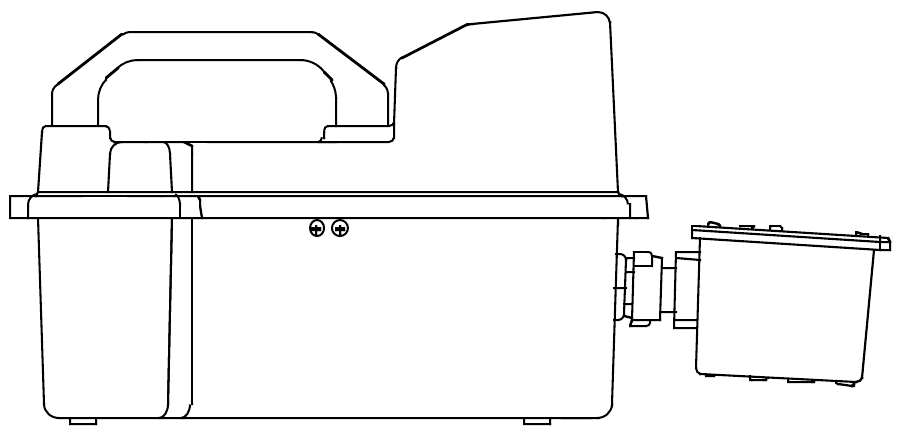
Description: Eagle and Remote Detector Eagle Case The Eagle has a plastic case with a full-sized handle. The high-visibility case is shielded to reduce radio frequency and electromagnetic interference (RFI/ EMI). The system is light-weight and balanced, which makes the Eagle easy to carry and use for extended periods. A foam rubber gasket between the top and bottom case components is water- and dust-resistant. You can set the case into 2.5 in. of water without damage.
Alarm Lights Two ultra-bright, red, light-emitting diodes (LEDs) provide visual alarms for gas concentrations and malfunctions. They are mounted on the top rear of the case for greatest visibility. Battery Charger Connector The battery charger connector is mounted on the top right rear of the case. The external battery charger connects to this connector to recharge nickelcadmium (Ni-Cd) batteries. The continuous operation adapter also connects to the battery charger connector.
Methane Elimination Switch The methane elimination switch (SW1) is mounted near the top right corner of the main PCB. For applications where methane is an interfering gas, you can set the methane elimination switch to eliminate most response to methane (see “Appendix B: Methane Elimination” on page 58). An external methane elimination switch is available as an option. CAL/SETUP Switch The CAL/SETUP switch (SW2) is mounted near the middle left edge of the main PCB.
Combustible, Shown w/out Bracket Oxygen H2S CO CN4 (H2S) CN1 (CO) Interconnect PCB CN2 (Oxygen) CN5 (Buzzer) CN6 CN3 (Combustible) Interconnect Circuit Board The Remote Detector has a printed circuit board (PCB) located inside its case, the interconnect PCB. The PCB is mounted perpendicular to the base of the Remote Detector’s case. It is positioned near the connector used to attach the Remote Detector to the Eagle.
Sensors Under normal conditions, the Eagle’s standard sensors have an operating life of approximately two years. To replace the sensors, open the case by unscrewing the four screws that secure the lid to the case. (See “Replacing Sensors” on page 52 for more details.) Combustible gas sensor The combustible gas (LEL) sensor is mounted with the flame arrestor extending outside the case to allow the ambient air to diffuse into the sensor. Five pins extend from the top of the sensor.
Standard toxics (CO and H2S) sensors The carbon monoxide (CO) and hydrogen sulfide (H2S) sensors are physically very similar. They both have cylindrical bodies and they are mounted with their faces behind a perforated hole pattern covered by a hydrophobic membrane to allow the ambient air to diffuse into the sensors. The CO sensor connector connects to the CO (CN1) socket and the H2S sensor connector connects to the H2S (CN4) socket on the interconnect PCB.
Operation The Eagle has four operating modes: normal operating mode, display mode, setup mode, and calibration mode. This section describes the Eagle in normal operating mode. It includes procedures to start up the Eagle, set various detection options for the combustible gas channel, and shut down the Eagle. NOTE: The screens illustrated in this section are intended as examples only. The screens displayed by your Eagle model may be slightly different. Starting Up the Eagle 1.
• To attach the Remote Detector directly to the Eagle, position the Remote Detector coupling in the unlocked position as shown below. Then line up the tab inside the connector on the Remote Detector with the notch inside the connector on the Eagle. Gently push the Remote Detector toward the Eagle. Turn the coupling clockwise on the connector of the Remote Detector to secure the Remote Detector to the Eagle’s bottom case assembly.
NOTE: If the Remote detector has been disconnected from the Eagle for more than a few minutes, such as during shipment, wait 15 minutes after connecting the Remote detector before turning on the Eagle to allow the CO and H2S sensors to stabilize. • To attach the Remote Detector using an extender cable, carefully fit the end of the extender cable that has a coupling to the Eagle’s connector. Make sure to line up the tabs inside the coupling with the matching notches in the cable connector as shown below.
Extender Cable 2. Press and briefly hold down the POWER/ENTER button. If the Lunch Break feature is on (see page 38), the Resume Datalog screen displays. (If the Lunch Break feature is off, the Battery Voltage screen displays.) R ESUME YES : NO : D A T A L OG 5 ? A I R D I SP L AY • Press the AIR/▲ button to continue accumulating time-weighted average (TWA) and PEAK readings from the last time the Eagle was used. (The short-term exposure limit [STEL] reading is reset each time the Eagle is turned on.
NOTE: The following screen only displays if the data logging option is installed. If the data logging option is not installed, the Self Diagnosis screen displays after the Battery Voltage screen. This message displays the date and time as set in Setup mode. The data logging option uses this information to record the time and date of sample and alarm events. A P R 17 1998 14 : 30 The following two screens display while the Eagle checks itself for proper operation.
3. Verify that the Eagle is operating correctly. Use the RKI Bump Test Kit to easily verify correct operation of the Eagle. WARNING: If the Eagle does not respond to verification, take it to a known “fresh-air” environment, then perform the demand zero procedure described in “Preparing for Calibration” on page 46. Repeat step 3 before using the Eagle in a potentially hazardous location.
Monitoring Combustible Gases Other than Methane If the combustible gas sensor is calibrated to methane (CH4), use Table 4 to determine the concentration of combustible gases other than methane. This table is based on Eagles in full response mode (methane elimination switch set to CH4) and calibrated to methane. Multiply the display reading by the factor in the appropriate column in the table.
Setting User Access The CAL/SETUP switch controls the Eagle functions available to the user. The switch setting does not affect the Eagle’s ability to display gas readings and indicate gas and malfunction alarms. 1. Turn off the Eagle. 2. Unscrew the two large screws on the top of the case. 3. Turn over the top half of the case, and locate the CAL/SETUP switch (SW2) near the middle along one edge of the main processor board.
Alarms Alarm Indications This section describes the Eagle’s audible and visual alarm indications for gas, over range, low battery, and sensor failure alarms. This section also describes how to reset gas alarms. The default alarm settings are listed in Table 2, “Standard Sensor Specifications” on page 4. The alarm settings are user-adjustable as described in “Updating the Alarm Point Settings” on page 36. NOTE: The screens illustrated in this section are intended as examples only.
STEL alarm (toxics only) If a toxic gas channel’s average gas reading for the past 15 minutes exceeds the STEL alarm setting: CH4 OXY H2S CO 0 20 . 9 15 . 0 0 LEL% VOL% PPM S T E L PPM • STEL displays in the alarm field for that channel. • The channel’s display line flashes. • The buzzer sounds a pulsed tone. • The alarm lights flash. TWA alarm (toxics only) If a toxic gas channel’s average gas reading for the past 8 hours exceeds the TWA alarm setting: CH4 OXY H2S CO 0 20 . 9 10 .
Low battery alarm When the battery charge drops near the lower limit, the Eagle displays the following screen (BAT flashes). For alkaline batteries, you have approximately 3 hours of use remaining; for Ni-Cd batteries you have approximately 15 minutes of use remaining. B A T CH4 OXY H2S CO 0 20 . 9 0 . 0 0 LEL% VOL% PPM PPM Low Battery Warning When the battery voltage drops to the minimum limit, the following screen displays, the alarm lights are on continuously, and the buzzer sounds a steady tone.
If the sensor failed during start-up, the Eagle continues with the normal start-up sequence after the fail screen displays. When the normal screen displays, the Eagle replaces the gas reading for the failed sensor with xxxxx. If the sensor fails during normal operation and you want to continue monitoring for the remaining target gases, turn the Eagle off, then follow the appropriate start-up sequence. When the normal screen displays, the Eagle replaces the gas reading for the failed sensor with xxxxx.
Display Mode The Eagle has four operating modes: normal operating mode, display mode, setup mode, and calibration mode.
To enter a user and station ID: To scroll to the next screen at any time, press the DISP/ADJ button. 1. Press the POWER/ENTER button. The first character under USER ID flashes (* is default). 2. Press the AIR/▲ and SHIFT/▼ buttons to scroll through the available characters. (The asterisk and blank space are between the set of letters and numbers.) 3. When the desired character displays, press the POWER/ENTER button to enter the character and go to the next character. 4.
TWA/STEL Screen The TWA/STEL screen displays the time-weighted average (TWA) and the short-term exposure limit (STEL) readings for toxic gases only. The TWA reading is the average reading during the last 8 hours. If 8 hours have not elapsed since the last time the TWA/STEL reading was cleared, the average is still calculated over 8 hours. The missing time is assigned a 0 value for readings. The STEL reading is the average reading during the last 15 minutes. T WA H2S CO 0 . 0 0 STEL 0 .
Clear Data Logger Screens CAUTION: Once you clear the Data Logger, you cannot retrieve any data previously stored in the Data Logger. The Clear Data Logger screens allow you to clear the Data Logger storage to accept new data. (Press the DISP/ADJ button to go to the Remaining Log Time screen). You can set the Eagle to overwrite the oldest data when the data log is full (see page 42). C L E AR D A T A L OGG E R ? YES : A I R NO : D I SP L A Y To clear the data log: 1.
Setup Mode NOTE: The screens illustrated in this section are examples only. The screens displayed by your Eagle model may be slightly different. The Eagle has four operating modes: normal operating mode, display mode, setup mode, and calibration mode. This section describes the setup mode.
Tips for Using Setup Mode • To select a menu option, use the AIR/▲ or SHIFT/▼ button to place the prompt next to the menu option, then press the POWER/ENTER button to select the menu option. • To exit setup mode, from the main menu place the prompt next to the last menu option, START MEASUREMENT, then press the POWER/ENTER button. The Eagle begins its normal start-up sequence. Entering Setup Mode WARNING: The Eagle does not detect gas or display readings while in setup mode.
2. Press the AIR/▲ or SHIFT/▼ button to display the desired setting. CAUTION: This setting should always match the type of batteries (alkaline or Ni-Cd) installed in the Eagle. If this setting does not match the installed batteries, the time between low battery warning and low battery alarm may be less than expected. 3. Press the POWER/ENTER button to enter the setting and return to the main menu.
5. Press the POWER/ENTER button to enter the new target gas label. A screen displays that shows the full-scale PPM setting, which corresponds to 100% LEL, and display increments for the target gas label you selected. If you select *** as the gas label, you must update the fullscale PPM setting to correspond to 100% LEL for the target gas. The number in parenthesis indicates the display increment for that portion of the PPM range.
3. Press the POWER/ENTER button to enter the displayed character. The next character flashes. 4. Repeat steps 2 and 3 to enter the remaining characters. When you enter the last character, the prompt flashes. Updating the full-scale PPM setting CAUTION: The full-scale PPM setting must correspond to 100% LEL for the target gas in order for the Eagle to display accurate PPM readings for the combustible gas channel. 1.
Returning to the main menu 1. Press the SHIFT/▼ button. The ESCAPE message displays. (Press the AIR/▲ button to return to the previous screen.) 2. Press the POWER/ENTER button to save the new setting. The OTHER GAS SET message displays, then the Gas Combinations menu displays. 3. To exit the Gas Combinations menu, press the SHIFT/▼ button until the prompt is next to Channel 4, then press SHIFT/▼ again. The ESCAPE message displays. 4. Press the POWER/ENTER button.
Updating the full-scale setting 1. Press the SHIFT/▼ button to place the prompt in the second line, then press the POWER/ENTER button to update the full-scale setting. The full-scale setting flashes. The maximum full-scale setting for the oxygen channel is 40.0 VOL%; the minimum setting is 25.0 VOL%. The default setting is 40.0 VOL%. 2. Press the AIR/▲ and SHIFT/▼ buttons to display the desired full-scale setting, then press the POWER/ENTER button to enter the setting. The prompt flashes.
Updating the target gas label 1. From the main menu, select the GAS COMBINATIONS menu option. 2. Press the POWER/ENTER button to display the Gas Combinations menu. > CH4 OXY H2S CO 3. Use the AIR/▲ or SHIFT/▼ button to place the prompt next to the toxic gas channel (in this example H2S or CO). 4. Press the POWER/ENTER button. The toxic target gas label flashes. This indicates that this setting can now be updated. 5.
Updating the full-scale setting 1. Press the SHIFT/▼ button to place the prompt in the second line, then press the POWER/ENTER button. The full-scale setting flashes. The maximum full-scale setting for a toxic gas channel is 1000 PPM; the minimum setting is 1.00 PPM. The default setting is 10.0 PPM. 2. Press the AIR/▲ and SHIFT/▼ buttons to display the desired full-scale setting, then press the POWER/ENTER button to enter the setting. The prompt flashes.
Updating Combustible Gas Channel Units of Measure This setting allows you to display the combustible gas reading in percentage of LEL or percentage of volume. The detection range remains the same. If 100% LEL equals 5% by volume, then full-scale on the volumetric display is 5%. 1. From the main menu, select the LEL% OR VOL% (HC) menu option. L E L% OR ( VOL% HC ) L EL% 2. Press the AIR/▲ or SHIFT/▼ button to display the desired setting.
If this is the alarm point you want to update, continue with step 3. If not, continue pressing the POWER/ENTER button until the correct set alarm point screen displays, then continue with step 3. 3. Use the AIR/▲ and SHIFT/▼ buttons to display the desired setting. 4. Press the POWER/ENTER button to enter the new alarm point and scroll to the next set alarm point screen. (Repeat step 3 and 4 to update another alarm point for this channel.) 5.
Updating the Lunch Break Setting With Lunch Break OFF (default), the Eagle automatically starts new TWA and PEAK reading collection at start up. With Lunch Break ON, the RESUME screen displays during start up. From this screen, you can choose to continue accumulating TWA and PEAK readings from the last time the Eagle was used or start collecting new readings. 1. From the main menu, select the LUNCH BREAK menu option. L UNCH BR EA K OFF 2. Press the AIR/▲ or SHIFT/▼ button to display the desired setting.
Updating the Alarm Silence Setting NOTE: This feature works only when Alarm Latching is turned on. With Alarm Silence ON, pressing the RESET/SILENCE button silences the buzzer when the Eagles goes into alarm. The LEDs continue to flash, and the display continues to show the level of alarm. With Alarm Silence OFF, you cannot silence the buzzer. 1. From the main menu, select the ALARM SILENCE menu option. A L A RM S I L ENC E ON 2. Press the AIR/▲ or SHIFT/▼ button to display the desired setting. 3.
Updating the Auto Calibration Settings The Eagle stores default calibration settings. This allows you to calibrate all Eagle channels simultaneously with a calibration cylinder that contains all required target gases (for example the RKI four-gas calibration cylinder). The Eagle includes default auto calibration settings for most target gases. For gases without default auto calibration, the setting is 0. NOTE: You can also update auto calibration settings in Calibration mode.
Updating the Back Light Setting This setting indicates the length of time the LCD illuminates when you press any button. The minimum setting is off; the maximum setting is 10 minutes. The default setting is 15 seconds. 1. From the main menu, select the LCD BACK LIGHT TIME menu option. LCD BACK L I GH T T I ME 15 SEC 2. Press the AIR/▲ and SHIFT/▼ buttons to display the desired setting. 3. Press the POWER/ENTER button to enter the setting and return to the main menu.
Updating the Interval Time Setting (data log option) This setting indicates how often the Eagle records readings into the Data Logger. The minimum setting is 10 seconds; the maximum setting is 5 minutes. The default setting is 5 minutes. 1. From the main menu, select the INTERVAL TIME menu option. S E T D A T A L OGG E R I NTERVA L T I ME 5 MI N 2. Press the AIR/▲ and SHIFT/▼ buttons to display the desired setting. 3. Press the POWER/ENTER button to enter the setting and return to the main menu.
Updating the Time Calibration Setting (data log option) This setting indicates how often the Eagle alerts you to needed calibration. The minimum setting is 1 day; the maximum setting is 180 days. The default setting is “off”. Tip: Press and hold the AIR/▲ or SHIFT/▼ button to rapidly scroll through settings. 1. From the main menu, select the TIME CALIBRATION menu option. SET CAL I BRA T I ON R EQU E S T T I M E o f f DAYS 2. Press the AIR/▲ and SHIFT/▼ buttons to display the desired setting. 3.
Updating the Confirmation Beep Setting With Confirmation Beep ON, the Eagle beeps once every 15 minutes to verify that it is operating. With Confirmation Beep OFF (default), the Eagle does not sound a confirmation beep. 1. From the main menu, select the CONFIRMATION BEEP menu option. CO N F I R MA T I O N BEEP OFF 2. Press the AIR/▲ or SHIFT/▼ button to display the desired setting. 3. Press the POWER/ENTER button to enter the setting and return to the main menu.
To reset all default alarm point settings: 1. From the main menu, select the DEFAULT menu option. The Set Default All screen displays. 2. Press the DISP/ADJ button to display the Set Default Alarm screen. DEFAUL T A L A RM YES : A I R NO : D I SP L A Y SET 3. Press the AIR/▲ button to reset all alarm points to their default settings. The messages SAVING DATA and END display, then the main menu displays. To reset the oxygen zero setting: 1. From the main menu, select the DEFAULT menu option.
Calibration Calibrate the Eagle when you replace a sensor. Also calibrate the Eagle periodically to assure proper sensor response. You can program the Eagle to notify you when it is due for calibration (see “Updating the Time Calibration Setting” on page 43). The frequency of calibration depends upon the amount and type of use. A typical calibration frequency is once per month.
Calibrating the Eagle Press and hold the SHIFT/▼ button, then press the DISP/ADJ button. The Calibration menu displays. NOTE: The following screens illustrate a four-gas Eagle with the data logging option and are intended as examples only. Your Eagle may display slightly different screens. AUTO CA L I BRAT I ON 50 LEL% The Eagle’s Calibration menu includes two methods of calibration: Auto Calibration and Single Calibration.
3. To adjust the values on the screen, hold down the SHIFT/▼ button, and press the DISP/ADJ button. The Auto Calibration screen for the combustible gas channel displays. C A L . CH4 OXY H2S CO 5 12 . 25 . 5 0 0 0 0 LEL% VOL% PPM PPM 4. Use the AIR/▲ (increase) and SHIFT/▼ (decrease) buttons to set the correct combustible gas value. 5. Press the POWER/ENTER button to enter the new setting. The Auto Calibration screen for the next channel displays. 6.
12. Press the SHIFT/▼ button to place the prompt next to the NORMAL OPERATION menu option, then press the POWER/ENTER button to return to the normal screen. Calibrating with the Single Calibration method This section describes calibration using the Single Calibration method. To calibrate using the Auto Calibration method, see “Calibrating with the Auto Calibration method” on page 47. CAUTION: The single calibration method does not have a “FAIL” notification.
5. With the Eagle and Remote Detector properly set up for calibration (see “Preparing for Calibration” on page 46), screw the regulator onto the calibration cylinder to begin a flow of gas at 1.0 liters per minute. Let the gas flow for 90 seconds. NOTE: The combustible gas sensor is a general hydrocarbon sensor that responds to most flammable vapors and gases; the response will vary depending upon the substance. For best results, calibrate the Eagle to the target gas or vapor. 6.
Maintenance Displaying the Battery Voltage Check the battery voltage periodically. Replace or recharge the batteries before the voltage drops to 4.5 V. WARNING: Take the Eagle to a non-hazardous location before replacing or recharging the batteries. To display the battery voltage: 1. From the normal screen, press the DISP/ADJ button to enter display mode. 2. Press the DISP/ADJ button until the Battery Voltage screen displays. BA T T ERY MI N . 4 . 5V BA T T ERY 6 . 0V N OW 3.
Eagle battery charger can determine if alkaline batteries are installed and will stop charging them automatically. Using any other battery charger can result in alkaline battery leakage or explosion if alkaline batteries are accidentally charged. NOTE: Setup mode allows you to select between alkaline and Ni-Cd batteries. The two types of batteries have unique low battery alarm characteristics.
To CN3 To CN2 CO Sensor To CN4 To CN1 Combustibles Sensor H2S Sensor Charcoal Filter Filter Boot Oxygen Sensor Replacing the combustibles sensor Replace the combustibles sensor when: • The combustibles channel cannot be calibrated correctly. • The LEL reading cannot be set to 0 by the Demand Zero command. To replace the combustibles sensor: 1. Take the Eagle to a non-hazardous location, and turn the power off. 2. Remove the Remote Detector from the Eagle. 3.
4. Inside the Remote Detector case, unscrew the two screws that secure the retainer plate to the case using a screwdriver. 5. Locate the combustibles sensor. With the external connector pointing toward you, the combustibles sensor is at the top left corner of the Remote Detector case. 6. Unplug the four-wire connector (red/white/green/black) from the circuit board. Hold the circuit board down when pulling up on the connector. 7. Remove the sensor. Retain the O-ring for use with the replacement sensor. 8.
7. Remove the sensor. 8. Install the replacement sensor in reverse order. When plugging in the wire connector into the circuit board, make sure to line up the tabs on the end of the wire connector with the notches on the connector of the circuit board. Be very careful not to bend the pins. Replacing the H2S or CO sensor Replace the H2S or CO sensor when: • The H2S or CO channel cannot be calibrated correctly. • The H2S or CO reading cannot be set to 00 by the Demand Zero command.
6. Remove the sensor. 7. Install the replacement sensor in reverse order. When plugging in the wire connector into the circuit board, make sure to line up the tabs on the end of the wire connector with the notches on the connector of the circuit board. Be very careful not to bend the pins. NOTE: Verify that you installed the H2S or CO sensor in the correct position. If the sensors are not installed in the correct position, the top of the Remote Detector will not close correctly when it is replaced.
Appendix A: Parts List Table 6 lists part numbers for the Eagle’s replacement parts and accessories. Table 6: Parts List Part Number Description 07-7016RK O-ring, 0.614 ID x 0.070, Buna N 07-7156RK O-ring, 4.237 ID x .103 for Remote Detector Lid 13-0100RK Shoulder Strap 33-0157RK Filter Disk for Remote Detector Sensor Openings 47-1650RK Extender Cable, Diffusion, 20ft. 47-1652RK Extender Cable, Diffusion Eagle, 50 ft.
Appendix B: Methane Elimination For applications where methane is an interfering gas, you can set the Eagle to eliminate most response to methane. The methane elimination switch is a standard feature on the circuit board inside the top of the Eagle’s case. An external switch is available as an option. For this type of detection, the combustible gas channel must be programmed to display HEX or *** (see “Updating Channel Settings” on page 29.
3. Perform the demand zero procedure as described in “Preparing for Calibration” on page 46. Monitoring combustible gases other than hexane Use Table 7 to determine the concentration of combustible gases other than hexane. This table is based on Eagle’s in methane elimination mode (methane elimination switch set to HEX ON) and calibrated to hexane. Multiply the display reading by the factor in the appropriate column.
Appendix C: Installing the Optional Data Logger Board Appendix C describes the procedure to install the Eagle’s Data Logger board. The data logging feature is an optional accessory. NOTE: Although the Data Logger board may be installed in the field, RKI Instruments, Inc., recommends that you return the Eagle to the factory for Data Logger board installation. 1. Take the Eagle to a non-hazardous location, and turn the power off. 2. Unscrew the two large screws on the top of the case.
Diffusion Eagle Instruction Manual Appendix C: Installing the Optional Data Logger Board