Eagle 2 Data Logger Management Program Operator’s Manual Part Number: 71-0170RK Revision: C Released: 6/12/12 www.rkiinstruments.
Warranty RKI Instruments, Inc. warrants gas alarm equipment sold by us to be free from defects in materials and workmanship, and performance for a period of one year from date of shipment from RKI Instruments, Inc. Any parts found defective within that period will be repaired or replaced, at our option, free of charge.
Table of Contents Introduction . . . . . . . . . . . . . . . . . . . . . . . . . . . . . . . . . . . . . . . . . . . . . . . 1 System Requirements . . . . . . . . . . . . . . . . . . . . . . . . . . . . . . . . . . . . . . . 2 Installing the Eagle 2 Data Logger Management Program . . . . . . . . . . 3 IrDA Downloading Cable . . . . . . . . . . . . . . . . . . . . . . . . . . . . . . . . . . . . . 5 Installing an IrDA Adapter Cable . . . . . . . . . . . . . . . . . . . . . . . . . . .
Changing the Password . . . . . . . . . . . . . . . . . . . . . . . . . . . . . . . . . 63 Viewing, Printing, & Deleting Data in the Last Calibration Window . . 66 Viewing & Printing Last Calibration Data . . . . . . . . . . . . . . . . . . . . . 66 Deleting Last Calibration Data . . . . . . . . . . . . . . . . . . . . . . . . . . . . . 70 Calibrating An Eagle 2 With the Data Logging Software . . . . . . . . . . 73 Changing Eagle 2 Instrument Parameters . . . . . . . . . . . . . . . . . . . . . .
Introduction Using an advanced detection system consisting of up to six gas sensors, the Eagle 2 Gas Monitor detects the presence of combustible gases, oxygen (O2), carbon monoxide (CO), hydrogen sulfide (H2S), and 2 other gases simultaneously. The Eagle 2’s compact size and easy-to-use design make it ideally suited for a wide range of applications as described in the Eagle 2 Operator’s Manual. Please read the Eagle 2 Operator’s Manual first before using the Eagle 2 Data Logger Management Program.
CAUTION: The Eagle 2 detects oxygen deficiency and elevated levels of oxygen, combustible gases, carbon monoxide, and hydrogen sulfide, all of which can be dangerous or life threatening. When using the Eagle 2, you must follow the instructions and warnings in the Eagle 2 Operator’s Manual to assure proper and safe operation of the unit and to minimize the risk of personal injury.
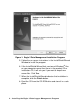
Installing the Eagle 2 Data Logger Management Program 1. Launch Windows®. 2. Exit from all applications and open windows. 3. There are two ways to install the Eagle 2 Data Logger Management Program: by using the Eagle 2 Product CD or by using the Eagle 2 Data Logger Management Program Installation CD. • If you are using the Eagle 2 Product CD, insert the Product CD in your computer’s CD-ROM drive. The CD will automatically open revealing several folders.
Figure 1: Eagle 2 Data Management Installation Program 5. Follow the on-screen instructions in the InstallShield Wizard Window to install the program. 6. If the InstallShield Wizard finds versions of Windows® files on your computer newer than those in the product CD or installation CD, it will ask you if you want to keep these newer files. Click Yes. 7. When the InstallShield Wizard indicates that installation is complete, click the Finish button. 8.
IrDA Downloading Cable The Eagle 2 communicates with a computer via an on-board infrared communication port that complies with IrDA protocol standards. NOTE: If your computer has a built-in infrared port, you do not need an adapter cable to download data. If your computer does not have an infrared port, you will need to install an IrDA/USB adapter cable on your computer to use the Eagle 2 Data Logger Management Program with your Eagle 2. The IrDA/USB cable is available from RKI Instruments, Inc.
Windows® Wireless Link Operation Note When using an IrDA adapter cable and the Eagle 2 Data Logger Management Program on a Windows® computer, it is necessary to make a special setting in the Wireless Link Configuration window for proper communication between the Eagle 2 and the Eagle 2 Data Logger Management Program. This must be done before attempting to use the program. Follow these steps to make this setting: 1. Click Start on the Windows® Icon Tray. 2.
Deselect Figure 2: Image Transfer Tab 6. Click OK. 7. Close the Control Panel window.
Launching the Program 1. Click Start on the Windows® Icon Tray, then select All Programs, then select Eagle 2. Your operating system may also have a shortcut installed in the Start menu. 2. The program will launch and the Download Window will appear. Figure 3: The Download Window 3. For convenience, make a shortcut of the Eagle 2 Data Logger Management Program and place it on the Windows® desktop. See your Windows® documentation for information about making shortcuts.
Control Buttons This section provides an overview of the control buttons. Instructions for using the various parts of the program accessed by the control buttons are given in other parts of this manual. When the program is launched, it opens in the Download Window. Along the right side of the Download Window are six control buttons that access other windows in the program.The figure below shows the various windows that you can access when you click the control buttons.
Download Button If you are in another program window, clicking the Download button opens the Download Window (see Figure 3). The Download window has several download commands that allow you to perform various data retrieval functions with an instrument that is connected to the program. Data can be retrieved from the instrument, data can be cleared from the instrument, and the instrument can be turned off.
commands and is currently connected to the program. If an instrument is turned off after being connected to the program, then the program will lose the connection with the instrument and the fields in the Instrument Information Window will become empty. Data Button Clicking the Data button opens the Data Window. Figure 6: Data Window In the Data Window, you can view, print, export, and delete data that has been downloaded from instruments.
• Interval Trend Data Files Interval trend data is logged at the interval time defined in the Eagle 2. Each logged point is an average reading over the previous time interval. • Alarm Trend Data Files Alarm trend data is logged around an alarm event. The Eagle 2 can save up to 8 alarm trend data files in its memory. • Alarm Event Files Alarm event files record gas alarm events that have been downloaded from instruments. The Eagle 2 can save up to 100 alarm events in its memory.
Last Calibration Button Clicking the Last Calibration button opens the Last Calibration Window. Figure 7: Last Calibration Window The Last Calibration Window stores the information for the most recent successful calibration for each Eagle 2 that has been downloaded. You can display the information three ways by using the Need Calibration, Calibration Date, or Calibration Record selection buttons. You can also print the information if you select the Need Calibration or Calibration Date display options.
Set Button Clicking the Set button opens the Set Window.
Downloading Data from the Eagle 2 You have the option of downloading data manually or automatically. If you want to download data using the automatic download feature, click the Automatic Download selection box in the Download Window before attempting to download data from the Eagle 2. Remember that if Automatic Download is selected, the Instrument Information Window will remain blank and the Eagle 2 will turn off automatically after the data has been downloaded.
IrDA adapter cable as shown in Figure 10 below, aligning the infrared port on the front of the Eagle 2 with the infrared port on the cable. Figure 10: Aligning the Eagle 2 with the Cable Infrared Receiver 3. Press and hold the POWER ENTER RESET button on the Eagle 2 until you hear a beep, then release it. The Eagle 2 will begin its power up sequence.
Power Off Download Commands become selectable. 5. If you are going to download data manually, you can perform a complete download, download only the instrument information, or download only the data files by using the Download Commands. • To download all data and instrument information from the instrument, click Complete Download. Figure 12: Download Commands • To download instrument information only, click Instrument Information. • To download all data, click Download Logger Data.
Use to download all data Use to download subsets of the data Clear data button Download messages Instrument ID Use to turn off Eagle 2 Figure 13: Download Messages & Download Commands 7. If the unit has been downloaded manually (Automatic Download not selected), the unit’s instrument information may be viewed after downloading by using the Instrument Information control button if the unit is still turned on and connected to the computer.
Figure 14: Instrument Information Window 8. You can view, print, export, or delete downloaded data by entering the Data or Last Calibration Windows. These windows are accessed by clicking Data or Last Calibration along the right side of the Download Window. See “Viewing, Printing, Exporting, and Deleting Data in the Data Window” on page 24 or “Viewing, Printing, and Deleting Data in the Last Calibration Window” on page 66. 9.
WARNING: If you click Clear Logger Data, all data is erased in the Eagle 2, but not in your computer’s memory. So it’s advisable that you download the data from the Eagle 2 first before clearing the data.
Overwriting Data in the Eagle 2 The Eagle 2’s Data Log Overwrite function is factory set to On so that when the Eagle 2’s data logging memory becomes full, it begins to overwrite the oldest interval trend data with new internal trend data. Download data regularly to avoid overwriting data in the Eagle 2 before it can be downloaded. The Data Log Overwrite function is accessible using the Eagle 2 Setup Mode. To set the Data Log Overwrite function to Off, see the Eagle 2 Operator’s Manual.
Viewing Data in the Instrument Information Screen You can view information for an instrument that has been downloaded and is currently connected by using the Instrument Information Window. Information cannot be printed or deleted in this window. Once the instrument is turned off, the Instrument Information Window becomes blank. Access the Instrument Information Window by clicking the Instrument Information button along the right side of the program window. The Instrument Information Window will display.
• Gas - Lists each channel’s gas in the order it appears on the Eagle 2 screen. • Calib. Date - Shows the date and time of the most recent successful calibration for each channel. • Before — shows the gas response prior to calibration. • After — shows the gas response after calibration. • A. Cal. — lists the auto-calibration setting for each channel of the Eagle 2. If a Eagle 2 passes its calibration, the “After” column should match the “A. Cal.” column.
Viewing, Printing, Exporting, and Deleting Data in the Data Window The Eagle 2 logs four types of data files: calibration history, interval trend data, alarm trend data, and event data. You can view, print, and export (save to a file) each of these types of data files. All of these types of data files can also be deleted. The deleting of files is password protected and is described in “Deleting Data in the Data Window” on page 60.
The Data Window is divided into four frames. The upper left frame is the Data Frame and displays all the data folders. They are grouped under the Eagle 2 icon in the upper left part of the frame. If the data folders are not visible, double click the Eagle 2 icon to make them visible. If no data has been saved, then no folders will appear when the Eagle 2 icon is double clicked. The lower left frame contains three selection boxes for organizing data.
Calibration History The Eagle 2 is capable of saving calibration information for up to the 100 most recent calibrations. This calibration history is retrieved by the Data Logger Management Program when data is downloaded from the Eagle 2 using either the Complete Download download command or the Download Logger Data download command. Instrument calibration information is also available in the Last Calibration Window.
To view, print, or export the calibration history for any instrument in the database: 1. With the software already launched, click the Data control button along the right side of the program window. The Data Window will appear. Double-click to show data folders Click to expand folder Click to show Cal. Histories File Cal. Histories file Figure 17: Data Window - Selecting Calibration History Files 2.
below the untitled folder along with the Alarm Events and Trouble Events folders. 5. Click the Calibration History folder. The Calibration Histories file or files for that instrument will appear in the top right frame. If multiple Station ID’s or User ID’s are used for an instrument, then more than one Calibration Histories file will appear. 6. Click a file to select it.
9. If you want to print the data, click the Print button. A Printer List dialog box will appear for you to select a printer. Figure 19: Printer List Dialog Box, Calibration History 10.Select a printer and click OK to print the data. 11.To export the data for use in another application, for example a spreadsheet or database, click the Export button. A “Save As” dialog box will appear for you to specify the filename, file type, and file location. The default file type is “.csv” (commaseparated values).
After specifying the file name, file type, and file location click the Save button to save the file to the specified location. 12.To go back and view other data, click the Return button in the upper right corner of the Data Window or the Data control button on the right side of the program window and select the data you want to view.
To view, print, or export the event data for any instrument in the database: 1. With the program already launched, click the Data control button along the right side of the program window. The Data Window will appear. Double-click to show data folders Click to expand folder Click to show alarm event file Alarm event file Figure 21: Data Window - Selecting Event Data Files 2. If necessary, double-click the Eagle 2 icon in the top of the Data Window’s upper left frame to see the folders of downloaded data.
untitled folder. The Alarm Events Folder and Trouble Events Folder will appear below the untitled folder along with the Calibration History Folder. 5. Click the Alarm Events or Trouble Events folder. One or more alarm or trouble event files will appear in the top right frame. An Alarm Events Folder has been opened in the example in Figure 21. If multiple User IDs or Station IDs are used for an instrument, then more than one event file will appear. 6. Click the desired event file to select it.
Figure 23: Data View - Trouble Events 8. If you click the Summary button, the Data Window will split into two frames one above the other with the event list in the lower frame and the summary information shown in the upper frame. The summary information is the same as the information shown in the upper right frame in Figure 21. The summary information is the instrument serial number, station ID, user ID, and the last download date. To return to the one frame format, click Summary again. 9.
11.To export the data for use in another application, for example a spreadsheet or database, click the Export button. A “Save As” dialog box will appear for you to specify the filename and file location. The default file type is “.csv” (comma-separated values). Figure 25: Save as Dialog Box 12.After specifying the file name, file location, and file type click the Save button to save the file to the specified location. 13.
An interval trend data file is created and saved in the Eagle 2 when the instrument is turned off or when a user ID, station ID, or catalytic combustible channel gas configuration (using the relative response feature in Display Mode) is changed during operation. The serial number, user ID, station ID, and catalytic combustible channel configuration that are entered in the instrument when it is turned on or that are updated during operation are saved for the corresponding interval trend file.
To view and perform desired operations with the interval trend files: 1. With the program already launched, click the Data control button along the right side of the program window. The Data Window will appear. Double-click to show data folders Click to expand folder Click to show interval trend files Interval trend files Figure 26: Data Window - Selecting Interval Trend Data Files 2.
dated folder whose contents you want to see. 5. Click on the Interval Trend Folder. In the upper right frame of the Data Window, a list of file names will appear in the Name column. A prefix of “iv” indicates an interval trend data file. 6. Click one of the interval trend data file names. A summary will appear in the bottom right frame with instrument and alarm setting information.
• In table format, the interval trend data is shown as the average gas readings over the user defined interval trend time. So if the data logging session started at 4:13:38 PM and the interval time is set to 1 minute, then the readings logged at 4:14:38 PM are the average reading for each channel over that one minute period. • Events are displayed on the screen under the channel in which they occur and with the time of the event.
• The catalytic combustible channel can be recorded in %LEL, ppm, or %volume units depending on the instrument setting. When viewing the interval trend data in table format, the units are displayed as the unit the reading was recorded in.
• If installed, an infrared methane or hydrocarbon channel records data in %LEL and/or % volume units depending on whether the channel is configured as a % LEL channel or a %LEL/% volume autoranging channel. When viewing the interval trend data in table format, the units are displayed as the unit the reading was recorded in. In the following figure, the first channel is a catalytic LEL channel and the fifth channel is an IR autoranging CH4 channel.
8. When the data is viewed in table format, if you move the cursor over an alarm event, it will change into a small symbol that looks like an alarm trend data file while it is kept over the alarm event.
If you click on the event, the corresponding alarm trend data file will be opened in a new window that pops up over the Data Window. No control buttons will be visible along the right side of the new window when an alarm trend data file is displayed in this way. To return to the interval trend data file, click the Return button or click the “X” in the upper right corner of the new window to close the window. Click to return to interval trend data Figure 31: Data Displayed by Alarm Trend Cursor Symbol 9.
• If there are more than two consecutive data points with the same readings for all channels, only the first and last of these consecutive data points are shown. • All events, such as gas alarms or sensor failures, are shown. • For any event, the data point before and after the event is always shown. 11.To view the data in graph format, click the Graph selection button. Five or more scheduled data points are required in an interval trend data file to be able to display it in graph format.
Zoom Level Event Select Cursor Feature Catalytic Combustible Channel Reading Units Figure 32: Interval Trend Data in Graph Format When viewing interval trend data in graph format, you have several options: • You can choose which gas(es) you want to graph by selecting or deselecting the boxes next to each gas name. The color of the gas name corresponds with its color on the graph and on the scale. • You can choose the zoom level, or displayed time interval, on the graph.
session and on the zoom factor. Depending on the length of the data session, data sessions that show changing readings will normally have more choices for zoom levels than sessions that show stable data to allow for viewing of gas reading changes in greater detail. • When selected, the Event feature shows on the graph where each channel went into and out of alarm and at what concentration each event occurred.
channel is the first channel and is displayed in green. Zoom Level Event Select Cursor Feature Catalytic Combustible Channel Reading Units Figure 33: Interval Trend Data in Graph Format • If installed, an IR HC or CH4 channel can be graphed in %LEL or % volume in order to accurately depict the full range of the sensor. If the channel is configured as a %LEL only channel, then data will only be recorded in %LEL and the range will be 0100% LEL. Any gas concentration above that level will not be recorded.
%LEL up to 100% LEL and then it will start recording data in % volume up to 100% volume. If %LEL is chosen as the graphing units, all data collected for a %LEL only channel will be displayed. Any data collected in an autoranging configuration that exceeds 100% LEL will not be shown. In order to view data above 100% LEL, % volume must be selected. When % volume is selected, all data will be shown in terms of % volume.
Zoom Level Catalytic combustible channel reading units IR HC or CH4 Cursor feature autoranging sensor channel reading units Event select Figure 34: Interval Trend Data in Graph Format With Autoranging NOTE: The IR Range Select selection box in the lower right hand corner only appears if an IR HC or CH4 sensor is installed, is in use, and is set up for autoranging. If an IR HC or CH4 sensor is not installed, if its channel is turned off, or if the channel is set up for % LEL only, this box will not appear.
information shown in the lower right frame in Figure 26. To return to the one frame format, click Summary again. 12.To print the data, whether it is viewed in table or graph format, click the Print button. A Printer List dialog box will appear for you to select a printer. Figure 35: Printer List Dialog Box, Interval Data 13.Select a printer and click OK to print the data. Data displayed in Graph view will print as a graph and data displayed in Table view will print as a table. 14.
For Graph view, the export file type is Windows bitmap (.bmp). For Table view, the default file type is “.csv” (commaseparated values). After specifying the file name, file location, and file type, click the Save button to save the file to the specified location. 15.To go back and view other data, click the Return button in the upper right corner of the Data Window or the Data control button on the right side of the program window and select the data you want to view.
To view and perform desired operations with the alarm trend files: 1. With the software already launched, click the Data control button along the right side of the program window. The Data Window will appear. Double-click to show data folders Click to expand folder Click to show alarm trend files Alarm trend files Figure 37: Data Window - Selecting Alarm Trend Data Files 2. If necessary, double-click the Eagle 2 icon in the top of the Data window’s upper left frame to see the folders of downloaded data.
5. Click on the Alarm Trend Folder in the upper left frame. In the upper right frame of the Data window, a list of file names will appear in the Name column. A prefix of “al” indicates an alarm trend data file. 6. Click one of the alarm trend data file names. A summary will appear in the bottom right frame with instrument and alarm setting information. If you want to view, graph, print, or export the alarm trend data, double-click the filename or click the View Data button at the bottom of the window. 7.
• In table format, the log times are shown along with the peak (minimum for oxygen) gas readings for the previous five seconds. • The gas readings at the time of the alarm event around which the logged data are centered are highlighted in red and are the instantaneous readings at that time. • The catalytic combustible channel can be recorded in %LEL, ppm, or %volume units depending on the instrument setting.
• If installed, an infrared methane or hydrocarbon channel records data in %LEL and/or % volume units depending on whether the channel is configured as a % LEL channel or a %LEL/% volume autoranging channel. When viewing the alarm trend data in table format, the units are displayed as the unit the reading was recorded in. In the following figure, the first channel is a catalytic LEL channel and the fifth channel is an IR autoranging CH4 channel.
8. The Event Only and Condensed selection boxes are not selectable for alarm trend files. 9. To view the data in graph format, click the Graph button. An alarm trend file can always be graphed regardless of the number of logged points.
recorded in any of these units and stored in the same file, those readings may only be graphed in one unit at a time. If %LEL is chosen as the unit, any ppm or %volume data is converted and graphed as %LEL. The user may change back and forth between the units for the graph and still have all data shown. The CAT Range Select box is where the user may select %LEL, ppm, or % volume as the units for the graph.
range of the sensor. If the channel is configured as a %LEL only channel, then data will only be recorded in %LEL and the range will be 0-100% LEL. Any gas concentration above that level will not be recorded. If the channel is configured as a %LEL/% volume autoranging channel, then data will be recorded in %LEL and % volume where appropriate. It will record data in %LEL up to 100% LEL and then it will start recording data in % volume up to 100% volume.
Zoom level Cursor feature Catalytic combustible channel reading units IR HC or CH4 channel units Figure 42: Alarm Trend Data in Graph Format NOTE: The IR Range Select selection box in the lower right hand corner only appears if an IR HC or CH4 sensor is installed, is in use, and is set up for autoranging. If an IR HC or CH4 sensor is not installed, if its channel is turned off, or if it’s set up for % LEL only, this box will not appear.
• When selected, the Event feature shows on the graph where each channel went into and out of alarm and at what concentration each event occurred. • When selected, the Cursor feature allows you to display the gas reading and log time for each data point in the alarm trend file. As you use the left and right arrow buttons on your keyboard to move the cursor across the graph horizontally, readings at specific log times are displayed.
12.To export the data for use in another application, for example a spreadsheet or database (for table data) or a word processing or presentation program (for graph data), click the Export button. A “Save As” dialog box will appear for you to specify the filename, file location, and file type. Figure 44: Save as Dialog Box For Graph view, the export file type is Windows bitmap (.bmp). For Table view, the default file type is “.csv” (commaseparated values).
• Interval Trend and Alarm Trend data files To delete any of the above items in the Data Window: 1. With the program launched, click the Data control button on the right side of the program window. 2. Find the folder or file you want to delete. 3. Place the cursor on the folder or file you want to delete and click it with the right mouse button. The Delete box will appear. Figure 45: Delete Box 4. Click Delete with the left mouse button. The Password Window appears. Figure 46: Password Window 5.
the program is first installed is “rki”. The password is case sensitive. See “Changing the Password” on page 63 for instructions to change the password if desired. 6. When the password has been entered and Continue clicked, the Delete Data Window (if a folder is selected for deletion) or Delete Sample Window (if a file is selected for deletion) will appear asking you to confirm that you want to delete the selected folder or file.
Changing the Password CAUTION: Changing the password requires use of the Delete box. Take care to avoid accidentally deleting data if you decide to change the password. It is possible to change that password as follows: 1. Right-click a data folder, data file, or event file. The Delete box will appear. Figure 48: Delete Box 2. Click Delete with the left mouse button. The Password Window appears.
3. Click Change Password. The Password Window asks you to input the current password. Figure 50: Inputting Current Password 4. Type the current password, then click Current password. The Password Window asks you to input the new password. Figure 51: Inputting New Password 5. Type the new password and click New Password. The Password Window asks you to input the new password again to confirm it. Figure 52: Confirming New Password 6. Type the new password again, then click Confirm New Password.
7. Click OK when the program confirms that you have changed the password. Figure 53: Confirming New Password 8. Close the Password Window by clicking the red “X” in the upper right corner of the window.
Viewing, Printing, and Deleting Data in the Last Calibration Window You can access data on the most recent successful calibration for each instrument that has been downloaded in the Last Calibration Window. You can view, print (calibration date view option only), and delete this data in the Last Calibration Window. Viewing and Printing Last Calibration Data Open the Last Calibration Window by clicking Last Calibration along the right side of the program window.
Figure 54: Last Calibration Window: Need Calibration View Option The Need Calibration view option shows the following fields: • No. — lists, in numerical order, the sequence of Eagle 2s whose data have been downloaded to the program. The most recently downloaded Eagle 2 will be No. 1. • SerialNo — shows the serial number of the Eagle 2 that was downloaded. • UserID — shows the user ID of the Eagle 2 that was downloaded. • StationID — shows the station ID of the unit that was downloaded.
• Last Downloaded — shows when the last download took place for a unit using the MM/DD/YY format and a 12-hour clock. This parameter is displayed on the second display line for each unit downloaded. The Eagle 2s that are due for calibration (in the case of the Need Calibration view option, that will be all of them), will have their last calibration date highlighted in red. The Eagle 2s that have not been downloaded for more than 90 days will have their last download date highlighted in purple.
To print a list of the instruments shown in the Calibration Date view option along with their user ID and last calibration date, click the Print button. A Printer List dialog box will appear. Figure 57: Printer List Dialog Box, Calibration Date View Option Select a printer and click the OK button to print the instrument list. Calibration Record View Option Selecting the Calibration Record view option shows detailed calibration information for each Eagle 2’s most recent successful calibration.
• Before — shows the settings prior to calibration. • After — shows the settings after calibration. • A. Cal. — lists the auto-calibration setting for each channel of the Eagle 2. If a Eagle 2 passes its calibration, the “After” column should match the “A. Cal.” column. If the Eagle 2 fails calibration on any of its channels, those channels will retain the previous calibration information.
4. Click the row with the right mouse button. The Delete box appears. Figure 59: Delete Box 5. Click Delete with the left mouse button. The Password window appears. Figure 60: Password Window, Deleting Last Calibration Data 6. Enter the password and click the Continue button. The password when the software is first installed is “rki”. The password is case sensitive. See “Changing the Password” on page 63 for instructions to change the password if desired.
7. When the password has been entered and the Continue button clicked, the Delete History window will appear asking you to confirm that you want to delete the most recent calibration information for the selected instrument. Figure 61: Delete History Window 8. If you want to delete the calibration information, click Yes. The information will be deleted by the program. If you do not want to delete the calibration information, click No and the operation will be cancelled.
Calibrating an Eagle 2 With The Eagle 2 Data Logger Management Program An Eagle 2 can be calibrated using the Eagle 2 Data Logger Management Program. The calibration function is available in the Set window. To perform a calibration you will need a calibration kit. This section describes calibration using a calibration kit that includes a demand flow regulator.
CAUTION: Calibration using the Eagle 2 Data Logger Management Program should be done in a fresh air environment, an area free of combustible and toxic gases and of normal oxygen content (20.9%). If you suspect the area is not a fresh air environment, apply zero air to the instrument when performing a zero operation. To calibrate an Eagle 2, perform the following steps: 1. Install the Eagle 2’s probe on the inlet fitting. 2. Launch the Eagle 2 Data Logger Management Program. 3.
6. Click the Set button to display the Set window. Click to begin calibration of Eagle 2 Figure 62: Set Window 7. Click the Calibration button in the Eagle 2 Status frame. The Eagle 2’s pump will turn on. The Calibration frame will replace the Eagle 2 Status frame and the control buttons along the right side of the window will become inactive.
Click boxes to select channels for calibration Set Cal values to match gas cylinder Figure 63: Set Window With Calibration Frame 8. Use the selection boxes under the Select column to select the channels you want to calibrate. 9. Click the Zero button. The software will perform a zero adjustment setting the oxygen channel to 20.9% and all other channels to 0. 10.If an optional sensor is installed and its target gas is not included in the 3-gas or 4-gas mix, the span will need to be adjusted individually.
13.Connect the regulator to the Eagle 2 probe tube using the sample tubing provided with the calibration kit. 14.Allow the gas to flow for one minute. The current gas readings will be shown in the Current Reading column. 15.Click the Span button. The program will make the span adjustments. 16.Disconnect the tubing from the Eagle 2’s probe tube. 17.Remove the regulator from the cylinder. 18.
Off download commands will be selectable. Click the Instrument Information download command to retrieve the instrument information from the Eagle 2. If you wish to download data before making changes, click Complete Download instead of Instrument Information. 5. Click the Set button to display the Set Window. Use the Eagle 2 Status Frame and the Gas/Sensor Frame to change parameters stored in the Eagle 2.
the standard four gas section. 6. To change the serial number, click the serial number field and use the backspace key to remove the current entry, then type the new information. To change the station ID or user ID, click the drop-down menu and select the desired station or user ID. 7. To change the datalogging trend interval time, click on the down arrow in the Interval Trend Time Field and select the desired interval time in seconds. The available choices are 5, 10, 20, 30, 60, 180, 300, and 600 seconds.
2 by using the POWER ENTER RESET button on the Eagle 2 or by clicking the Power Off button and confirming that you want to turn off the Eagle 2 when the Power Off Window appears. Then click the Exit button to exit the software.
of Instrument Information. 5. Click the Set button to display the Set window.
Station & User Tab The Station & User tab displays a list of Station IDs and User IDs. The first time the Eagle 2 is connected to the Eagle 2 Data Logger Management Program, this list will be blank. No Station IDs or User IDs are loaded into the Eagle 2 at the factory. These are user-defined parameters that may only be configured using the Eagle 2 Data Logger Management Program. Up to 128 Station IDs and up to 32 User IDs may be defined.
CSV Files To edit the Station ID or User ID list, you will need to import a csv (comma separated values) file into the program. A Station csv file and a User csv file are provided with the program. In addition, you can generate csv files for editing from the program. 1. To create a csv file for editing, click the “Export csv file” button located to the right of the Station ID list or the User ID list.
2. Navigate to the location you would like to save the csv file, type in a file name, and click Save.
3. The csv files can be opened, edited, and saved using a word processing program such as Word, WordPad, or Notepad. The Station and User csv files consist of the Station or User ID number and its associated name. Below is an example of a Station csv file opened in WordPad. Figure 70: Station csv File Any existing Station or User IDs will be displayed. Undefined Station or User IDs will appear as dashes.
2. In the Station and User tab, click “Import csv file” for either the Station ID or User ID and select a csv file.
3. Select the file you want to import and click Open. Figure 72: Station csv File Save As 4. Once the Station ID and/or User ID lists have been imported, click OK to save changes and return to the Set window. If you do not want to save the changes, click Cancel. 5. The new station and user ID lists will be visible in the Station ID and User ID selection boxes in the Set window. Use the drop down menu to select a current station and user ID for the instrument. 6.
7. Click Yes in the confirmation window that appears. Figure 73: Update Confirmation Window Conversion Table Tab The Conversion Table tab is used to view the pre-defined relative response gases for the catalytic combustible channel and to edit or add user-defined gases. The pre-defined gases can be found in the Pre-Defined Table tab while the user-defined gases can be found under the User-Defined Table tab.
There are 8 columns in both the Pre-Defined Table tab and the User-Defined Table tab: • No This column represents the gas number. The gas numbers are 1-30. • Name This is what will appear in the Relative Response list of gases. The name can be up to 3 characters long and the characters must be upper case letters or numbers. No special characters may be used in the Name column. • Long Name The Long Name column is used to better describe the target gas. It may contain any character in upper- or lower-case.
NOTE: If you define a gas whose LEL is above 50,000 ppm, the %LEL reading in Measuring Mode will reflect the defined ppm ratio, but the ppm reading in Measuring Mode will not indicate above 50,000 ppm.
While the pre-defined gases may not be edited, the 5 userdefined gases may be edited by doing the following: 1. With the Data Logger Management Program running, click the Set button to display the Set window. Click the Detail Settings button to display the Detail Settings window. Click on the Conversion Table tab and then click on the UserDefined Table tab. Figure 75: User-Defined Table 2.
4. Open the csv file using Notepad, Word, or WordPad. The example below shows a csv file opened in WordPad. The list of gases are associated with the numbers 1-5. Figure 76: CSV File If there were no previously defined gases, the csv file will appear as the following: Figure 77: Blank CSV File 5. The values in the csv file are all separated by commas. These values are in the same order as the columns in the Data Logger Management Program. The first value is the gas number, the second is the gas name, etc.
7. Return to the Data Logger Management Program with the User-Defined Table tab still up and press “Import csv file”. 8. Choose the file you just edited and press “Open”. 9. The values you entered in the csv file will appear in the UserDefined Table. 10.If the program finds anything wrong with the values that were entered, the box containing those values will turn red. Make sure that you have entered valid characters for each field. 11.Click OK to save the changes and return to the Set window.
PID Sensor Tab The PID Sensor tab is used to view the pre-defined relative response gases and to view or define the 1 user-defined relative response gas. Every gas has a low and high range which are displayed in the Low Range tab and High Range tab, respectively. Figure 79: PID Sensor There are 13 columns in both the High and Low Range tabs: • No This column represents the gas number. They are numbered 1-17. • Name This is what will appear in the Relative Response list of gases.
• Full Scale This is the full scale value for the target gas. • Point The point value indicates to what decimal place the gas readings are shown. A value of 1/1 indicates a reading to the “ones” place while a value of 1/100 indicates a reading to the “hundredths” place. • Unit The unit describes what units the gas reading is provided in. All units are in ppm.
from Table 5 on page 102 or through testing as described in “Obtaining a Relative Response Factor” on page 101. A valid character for the Factor is a value between 0.01 and 25.00. There are limitations for the full scale and increment values that depend on the factor for both the high range and the low range. Table 2 and Table 3 below list these limitations. Table 2: High Range PID Factor Full Scale (ppm) Increment 0.25-0.36 1000 1 0.37-0.49 1500 1 0.50-0.61 2000 1 0.62-0.74 2500 1 0.75-0.
Table 3: Low Range PID Factor Full Scale (ppm) Increment 0.50-0.59 25.00 0.01 0.60-0.79 30.00 0.02 0.80-0.99 40.00 0.02 1.00-1.99 50.00 0.02 2.00-2.99 100.0 0.1 3.00-3.99 150.0 0.1 4.00-5.99 200.0 0.1 6.00-7.99 300.0 0.2 8.00-9.99 400.0 0.2 10.00 500.0 0.
While the pre-defined gases may not be edited, the 1 userdefined gas may be edited by doing the following: 1. With Data Logger Management Program running, click on the Set button to display the Set window. Click the Detail Settings button to display the Detail Settings window. Click on the PID Sensor tab and then click on the High Range tab. Figure 80: High Range Tab 2.
3. Export the current data by pressing the “Export csv file” button. Choose the file path you wish to save the file in. Figure 81: Save As 4. Open the csv file using Notepad, Word, or WordPad. The example below shows a csv file opened in WordPad. The user defined PID gas is number 17. Figure 82: CSV File 5. The values in the csv file are all separated by commas. These values are in the same order as the columns in the Data Logger Management Program.
6. Edit the values you wish to change and save the file. 7. Return to the Data Logger Management Program with the High Range tab still up and press “Import csv file”. 8. Choose the file you just edited and press “Open”. 9. The values you entered in the csv file will appear in the High Range tab. 10.If the program finds anything wrong with the values that were entered, the box containing those values will turn red. Make sure that you have entered valid characters for each field.
Obtaining a Relative Response Factor If the gas that you want to monitor on the catalytic combustible or PID channel is not included in the catalytic or PID relative response lists, you may define up to 5 gases for the catalytic combustible channel using the Conversion Table tab and 1 gas for the PID channel using the PID Sensor tab. Testing must be done using the desired target gas in order to obtain the response factor value for the catalytic combustible channel.
number • Formula-Molecular formula for each VOC • Response Factor (RF)-The relative response factor for each gas. This is the value that is plugged into the Eagle 2 Maintenance Data Loader Program. Some abbreviations that appear in the table are: • ZR-No response • NV-Cannot be measured Table 5: Response Factors Relative to Isobutylene Gas/ VOC CAS No. Formula Acetaldehyde 75-07-0 C2H4O Relative Response 4.
Gas/ VOC Biphenyl CAS No. Formula Relative Response 0.4 92-52-4 C12H10 7/5/38 C6H10O3 3 Boron trifluoride 7637 07 2 BF3 ZR Bromine 7726-95-6 Br2 20 Bromine pentafluoride 7789-30-2 BrF5 ZR Bromobenzene 108-86-1 C6H5Br 0.7 Bromochloromethane 74-97-5 CH2ClBr ZR Bis(2,3-epoxypropyl) ether Bromoethane 74-96-4 C2H5Br 5 6482-24-2 C3H7OBr 2.5 Bromoform 75-25-2 CHBr3 2.8 Bromopropane, 1- 106-94-5 C3H7Br 1.3 Bromotrifluoromethane 75-63-8 CF3Br ZR 0.
Gas/ VOC CAS No. Formula Chloro-1,3-butadiene, 2- 126-99-8 C4H5Cl Relative Response 3.2 Chloro-1-fluoroethane, 1- 1615-75-4 C2H4ClF ZR Chloro-2-fluoroethane, 1- 762-50-5 C2H4ClF ZR Chloroacetaldehyde 107-20-0 C2H3OCl ZR Chlorobenzene 108-90-7 C6H5Cl 0.5 Chlorodifluoromethane 75-45-6 CHClF2 ZR Chloroethane 75-00-3 C2H5Cl ZR Chloroethanol 2- 107-07-3 C2H5ClO 10 Chloroethyl methyl ether, 2- 627-42-9 C3H7ClO 2.
Gas/ VOC CAS No. Formula Dichloro-1,1-difluoroethane, 1,2Dichloro-1,2,2-trifluoroethane, 1,2Dichloro-1,2-difluoroethane, 1,2Dichloro-1-fluoroethane, 1,1- 1649-08-7 Relative Response C2H2Cl2F2 ZR 354-23-4 C2HCl2F3 ZR 631-06-1 C2H2Cl2F2 ZR 1717-00-6 C2H3Cl2F ZR Dichloro-1-fluoroethane, 1,1- 1717-00-6 C2H3Cl2F ZR Dichloro-1-fluoroethane, 1,2- 430-57-9 C2H3Cl2F ZR Dichloro-1-propene, 2,3- 78-88-6 C3H4Cl2 1.
Gas/ VOC CAS No. Formula Relative Response 1.1 Dimethyl cyclohexane, 1,2- 583-57-3 C8H16 Dimethyl disulphide 624-92-0 C2H6S2 0.2 Dimethyl ether 115-10-6 C2H6O 1.3 Dimethyl phthalate 131-11-3 C10H10O4 1 Dimethyl sulphate 77-78-1 C2H6O4S ZR Dimethyl sulphide 75-18-3 C2H6S 0.5 Dimethylacetamide N,N- 127-19-5 C4H9NO 1.3 Dimethylamine 124-40-3 C2H7N 1.4 Dimethylaminoethanol 108-01-0 C4H11NO 1.5 Dimethylaniline, NN- 121-69-7 C8H11N 0.
Gas/ VOC CAS No. Formula Ethyl hexanoate 123-66-0 C8H16O2 Relative Response 2.6 Ethyl hexanol, 2- 105-76-7 C8H18O 1.5 Ethyl hexyl acrylate, 2- 103-11-7 C11H20O2 1 Ethyl mercaptan 75-08-1 C2H6S 0.7 Ethyl octanoate 106-32-1 C10H20O2 2.3 Ethylene 74-85-1 C2H4 8 Ethylene dinitrate 628-96-6 C2H4O6N2 ZR Ethylene glycol 107-21-1 C2H6O2 20 Ethylene oxide 75-21-8 C2H4O 15 Ferrocene 102-54-5 C10H10Fe 0.
Gas/ VOC CAS No. Formula Relative Response 0.8 Hydroquinone 123-31-9 C6H6O2 Hydroxypropyl acrylate 2- 999-61-1 C6H10O3 1.5 Iminodi(ethylamine) 2,2- 111-40-0 C4H13N3 0.9 Iminodiethanol 2,2'- 111-42-2 C4H11NO2 1.6 Indene 95-13-6 C9H8 0.5 Iodine 7553-56-2 I2 0.2 Iodoform 75-47-8 CHI3 1.5 Iodomethane 74-88-4 CH3I 0.4 Isoamyl acetate 123-92-2 C7H14O2 1.6 Isobutane 75-28-5 C4H10 8 Isobutanol 78-83-1 C4H10O 3.5 Isobutyl acetate 110-19-0 C6H12O2 2.
Gas/ VOC CAS No. Formula Relative Response 1.2 Methoxypropyl acetate 108-65-6 C6H12O3 Methyl acetate 79-20-9 C3H6O2 5.2 Methyl acrylate 96-33-3 C4H6O2 3.4 1.9 Methyl bromide 74-83-9 CH3Br Methyl cyanoacrylate 137-05-3 C5H5O2N 5 Methyl ethyl ketone 78-93-3 C4H8O 0.8 Methyl ethyl ketone peroxides 1338-23-4 C8H18O2 0.8 Methyl formate 107-31-3 C2H4O2 ZR Methyl isobutyl ketone 108-10-1 C6H12O 0.
Gas/ VOC Nitropropane, 2Nitrous oxide CAS No. 79-46-9 Formula Relative Response C3H7NO2 ZR 10024-97-2 N2O ZR Nonane, n- 111-84-2 C9H20 1.3 Norbornadiene, 2,5- 121-46-0 C7H8 0.6 Octachloronaphthalene 2234-13-1 C10Cl8 1 Octane, n- 111-65-9 C8H18 1.6 Octene, 1- 111-66-0 C8H16 0.
Gas/ VOC CAS No. Formula Propylene oxide 75-56-9 C3H6O Propyleneimine 75-55-8 C3H7N 1.3 Pyridine 110-86-1 C5H5N 0.8 Pyridylamine 2- 504-29-0 C5H6N2 0.8 Silane 7803-62-5 SiH4 ZR Sodium fluoroacetate 62-74-8 C2H2O2FNa ZR Styrene 100-42-5 C8H8 0.4 9/5/46 SO2 ZR Sulphur hexafluoride 2551-62-4 SF6 ZR Sulphur tetrafluoride 7783-60-0 SF4 ZR Sulphuric acid 7664-93-9 H2SO4 ZR Sulphuryl fluoride 2699-79-8 SO2F2 ZR C18H14 0.
Gas/ VOC CAS No. Formula Tributylamine 102-82-9 C12H27N Relative Response 1 Trichloro-1,1-difluoroethane, 1,2,2Trichloro-1,2-difluoroethane, 1,1,2Trichloro-2,2-difluoroethane, 1,1,1Trichloro-2-fluoroethane, 1,1,2Trichlorobenzene 1,2,4- 354-21-2 C2HCl3F2 ZR 354-15-4 C2HCl3F2 ZR 354-12-1 C2HCl3F2 ZR 359-28-4 C2H2Cl3F ZR 120-82-1 C6H3Cl3 0.6 Trichloroethane, 1,1,1- 71-55-6 C2H3Cl3 ZR Trichloroethane, 1,1,2- 79-00-5 C2H3Cl3 ZR Trichloroethylene 79-01-6 C2HCl3 0.
Changing the Appearance of the Program Screens To change how information is displayed in the program (e.g., text font or graph colors), use the program’s Set Window. Follow the steps below to make changes. 1. Launch the Eagle 2 Data Logger Management Program. 2. Click the Set button to display the Set window. Use the Font And Color Frame in the left side of the window to change fonts and graph colors.
3. Specify new fonts by clicking the button with the name of a font inscribed on it. This action will display the Font Window. Choose the font type, style, size, and script, then click OK.
4. Select the colors used to graph the various target gases in the interval trend and alarm trend data files by clicking the appropriate Graph Color button on the left side of the Set Window in the Font and Color frame. The six Graph Color buttons correspond to the 6 possible Eagle 2 channels. From top to bottom, they correspond to channels 1-6. Figure 86: Color and Custom Color Windows • The Color Window shown on the left above appears when the Graph Color button is clicked.
Spare Parts List Table 6: Spare Parts List Part Number Description 47-5027RK Cable, USB/IrDA adapter 71-0170RK Eagle 2 Data Logger Management Program Operator’s Manual (this document) 71-8003RK Eagle 2 Product CD, Includes the Eagle 2 Data Logger Management Program, the Eagle 2 Maintenance Program, and Operator’s Manuals for Each 116 • Spare Parts List