
Manual


Digester Gas Monitor Operator’s Manual Parts List • 89
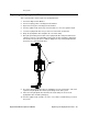
it in the socket.
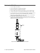
7. Plug in or turn on all incoming power to the Digester Gas Monitor.
8. Place the Digester Gas Monitor’s power switch in the ON position, then verify that the
PILOT light is on.
9. Close and secure the housing door.
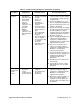
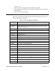
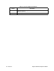
Parts List
Table 23 lists the part numbers and descriptions for replacement parts and accessories
offered for the Digester Gas Monitor.
Table 23: Parts List, Digester Gas Monitor
Part No. Description
06-1248RK Sample tubing (3/16 in. x 5/16 in.; specify length when ordering)
06-1251RK Sample tubing for aspirator/sample exhaust line (1/4 in. x 3/8 in.; specify
length when ordering)
18-0107RK Conduit hub (3/4 in.)
33-0164RK Oil mist filter
33-0167RK Air filter
33-0171RK Hydrophobic filter
33-0413RK Water trap
33-0413RK-02 Water trap filter element
43-0440RK Reset switch
43-4170RK Fast blow fuse, 6A, 250 V
51-0096RK Horn/strobe, 10-33 VDC, NEMA 4X
52-1016RK Buzzer
61-5040RK-05 IR CO
2
replacement plug-in sensor, 0 - 50% volume
61-5041RK-CH4 IR CH4 replacement plug-in sensor, 0 - 100% volume
65-2039RK H
2
S replacement sensor
71-0266RK Digester Gas Monitor Operator’s Manual (this document)
81-0013RK-05 Calibration cylinder, 50% vol. methane in nitrogen, 58-liter steel
81-0027-05 Calibration cylinder, 40% vol. CO
2
/ 60% vol. methane, 58-liter
81-0078RK-03 Calibration cylinder, 100% nitrogen, 103-liter
81-0145RK-02 Calibration cylinder, 500 ppm H
2
S, 58-liter
81-0145RK-16 Calibration cylinder, 500 ppm H
2
S, 116-liter