
Manual

Digester Gas Monitor Operator’s Manual Wiring the Digester Gas Monitor in a Modbus System • 69
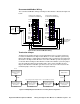
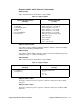
Recommended Modbus Wiring
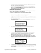
The recommended Modbus wiring for the Digester Gas Monitor is illustrated in Figure 20
below.
Figure 20: Recommended Modbus Wiring
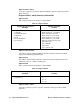
Termination Jumper
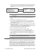
The Digester Gas Monitor includes a 2-pin termination header (see Figure 3) that may
need to be installed when the Digester Gas Monitor is used in a Modbus system. Every
Digester Gas Monitor is supplied with a termination jumper (a jumper block) installed onto
this header. If the Digester Gas Monitor is not used in a Modbus system, this jumper has
no function. When the Digester Gas Monitor is installed in a Modbus system, this jumper
must be installed in a Digester Gas Monitor that is at the end of a Modbus line. Any
Digester Gas Monitor in a Modbus system that is not at the end of a line must have the
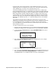
termination jumper removed (see Figure 21 & Figure 22 below).
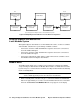
Figure 21: Multiple Digester Gas Monitors in a Daisy Chain Configuration
B
A
DP SW
DP SW
EXT DC
24V BATT
B
A
DP SW
DP SW
EXT DC
24V BATT
Digester Gas Analyzer
Controller Terminal Strip
Digester Gas Analyzer
Controller Terminal Strip
Common
D1
ALARM
BUZZER
ALARM
RESET
ALARM
BUZZER
ALARM
RESET
Modbus
Controller
C
RS-485
To Additiona
l
Digester Ga
s
Analyzers
Input
Terminals
D0
C
RS-485
ID=1ID=29
Modbus Master
RS-485
Up to 32 Digester Gas Analyzers can be connected without a repeater
ID=30
Digester Gas Analyzer
Termination Jumper
Not Installed
Digester Gas Analyzer
Termination Jumper
Not Installed
Digester Gas Analyzer
Termination Jumper
Not Installed
Digester Gas Analyzer
Termination Jumper
Not Installed
ID=31
RS-485
ID=32
Digester Gas Analyzer
Termination Jumper
Installed