
Manual


Digester Gas Monitor Operator’s Manual Alarm Indications • 41
NOTE: You can set the channel alarm relays to be either all normally energized or all
normally de-energized in the Global Menu. The following sections describe the
factory settings of normally de-energized for the channel relays. The fail relay is
factory-set as normally energized and is not user adjustable. See “Viewing and
Changing Global Parameters” on page 47 for instructions to change the channel
alarm relays.
Alarm 1 Condition
This section describes the indications for an alarm 1 condition and suggests responses to
an alarm 1 condition.
Alarm 1 Condition Indications
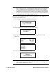
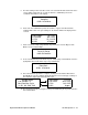
When the gas reading of an active channel reaches the alarm 1 setpoint, the Digester Gas
Monitor senses an alarm 1 condition. The Digester Gas Monitor alerts you to an alarm 1
condition as follows:
• the alarm 1 LED turns on
• the gas reading in alarm 1 condition alternates with the ALARM-1 message
• the buzzer sounds a pulsing tone
• the applicable alarm 1 channel relay energizes
• if installed and set to activate in an alarm 1 condition, the horn/strobe flashes and
sounds a pulsing tone
NOTE: The oxygen alarm 1 condition has a 30 second factory set delay. The delay may
be changed in the Configuration Menu.
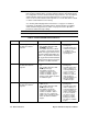
Fail • Disconnected or
misconnected
detector wiring
• Display reading below
-10% of full scale or
lower
• Malfunctioning
components
• Fail LED is on
• FAIL message replaces the
gas reading
• If installed and set to activate
for fail, horn/strobe flashes
NOTE: There is a 30 second delay
on the fail indications.
• Buzzer sounds a
steady tone
• If installed and set to
activate for a fail
condition, the horn/
strobe sounds a
pulsing tone
Flow Fail Flow to system falls
below 1.6 SCFH
• Display alternates between
FLOW FAIL and normal
screen
• If installed, the horn/strobe
activates
• A 60 second fresh air purge is
initialized
• Flow through system will be
stopped
• Buzzer sounds a
steady tone
• If installed, the horn/
strobe sounds a
pulsing tone
Low
Battery
No AC power and DC
power source (primary or
backup) less than 18.5
volts.
• FAIL LED is on
• Display shows LOW POWER
STANDBY message and the
input DC voltage
None
Table 6: Visual and Audible Alarm Indications
Condition Cause Visual Indication(s) Audible Indication