
Manual

Digester Gas Monitor Operator’s Manual Internal Description • 11
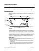
either AC or DC power.
• Fail LED
The fail LED turns on when the Digester Gas Monitor is experiencing a fail condition,
including a flow fail. See “Fail Condition” on page 44 and “Flow Fail Condition” on
page 44 for a description of these conditions.
•Alarm 1 LED
The alarm 1 LED is on when the Digester Gas Monitor is experiencing an alarm 1
condition.
•Alarm 2 LED
The alarm 2 LED is on when the Digester Gas Monitor is experiencing an alarm 2
condition.
•Alarm 3 LED
The alarm 3 LED is on when the Digester Gas Monitor is experiencing an alarm 3
condition.
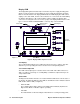
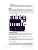
Control Switches
The Digester Gas Monitor includes four push button control switches that allow you to
enter the selection menus and Calibration Mode, navigate through the menus and
Calibration Mode, update instrument and channel parameter settings, and save changes
to the settings. The control switches, listed in Table 2, are to the right of the LCD display
(see Figure 4).
Table 2: Digester Gas Monitor Control Switch Functions
Button Function
ESCAPE • Moves backward through the menu and mode screens
• Aborts operations
• Cancels changes you make in the menus
• Enters the Configuration Menu (press with ENTER button)
• Enters the Global Menu (press with the UP/YES button)
UP (YES) • Initiates an operation or proceeds to the next screen when a yes/
no question is asked on a screen
• Changes the displayed setting
• Enters the Global Menu (press with ESCAPE) button
• Enters the Calibration Mode (press with ENTER button)
DOWN (NO) • Cancels an operation or sequence when a yes/no question is
asked on a screen
• Changes the displayed setting
• Enters the Modbus Menu (press with ENTER button)
ENTER • Saves changes you make in the menu and mode screens
• Accepts the displayed parameter setting
• Enters the Configuration Menu (press with ESCAPE button)
• Enters Calibration Mode (press with UP/YES button)
• Enters the Modbus Menu (press with DOWN/NO button)
• Initiates a manual detection cycle