
Manual

Digester Gas Monitor Operator’s Manual Internal Description • 9
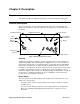
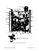
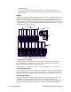
Figure 3: Digester Gas Monitor Component Location
Ho using
Mounting
Plate
F low Me te r ,
Flow to
Sensors,
0.6 - 5 SCF
H
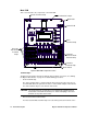
Main PCB
Hydrophobic
Filter
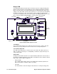
LCD
Pressure
Gauge
Re gul ator
Water Trap
Drye r
Di spla y PC B
Solenoid
Valve,
3 way
F low Me te r,
H2 S D ilu t ion
Sample,
.05 - .5 SCFH
Mounting
Foot, 4X
Ch eck V alv e
Flow Meter,
H2 S Dilu tion Air,
0.2 - 2.0 SCFH
Sol eno id Val ve, 2 W ay, 3X
Aspirator, Air-Vac
Flow Bl ock w ith Sen sors
Flow
Switch
Ho rn/Stro be
(Optional)
Compressed Air Filter/Water T rap
*Filter i s user
instal led. L ocationto be dete rmi ned at i nstall ati on.
Oil Mist Filter
Filter,
Particle