Digester Gas Monitor Operator’s Manual Part Number: 71-0266RK Revision: 0 Released: 10/9/14 www.rkiinstruments.
WARNING Read and understand this instruction manual before operating detector. Improper use of the detector could result in bodily harm or death. Periodic calibration and maintenance of the detector is essential for proper operation and correct readings. Please calibrate and maintain this detector regularly! Frequency of calibration depends upon the type of use you have and the sensor types.
Product Warranty RKI Instruments, Inc. warrants gas alarm equipment sold by us to be free from defects in materials, workmanship, and performance for a period of one year from date of shipment from RKI Instruments, Inc. Any parts found defective within that period will be repaired or replaced, at our option, free of charge.
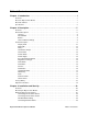
Table of Contents Chapter 1: Introduction . . . . . . . . . . . . . . . . . . . . . . . . . . . . . . . . . . . . . . . . . . . . . . . . 1 Overview . . . . . . . . . . . . . . . . . . . . . . . . . . . . . . . . . . . . . . . . . . . . . . . . . . . . . . . . . . . . . . . . . . . . About the Digester Gas Monitor . . . . . . . . . . . . . . . . . . . . . . . . . . . . . . . . . . . . . . . . . . . . . . . . . . About this Manual . . . . . . . . . . . . . . . . . . . . . . . . . . . . . . . . . . . . . . .
Connecting Recorders . . . . . . . . . . . . . . . . . . . . . . . . . . . . . . . . . . . . . . . . . . . . . . . . . . . . . . Making Fitting Connections . . . . . . . . . . . . . . . . . . . . . . . . . . . . . . . . . . . . . . . . . . . . . . . . . . . . . Compression Fitting Connections . . . . . . . . . . . . . . . . . . . . . . . . . . . . . . . . . . . . . . . . . . . . . Hose Barb Connections . . . . . . . . . . . . . . . . . . . . . . . . . . . . . . . . . . . . . . . . . . . . . . . . . . . . .
Recommended Modbus Wiring . . . . . . . . . . . . . . . . . . . . . . . . . . . . . . . . . . . . . . . . . . . . . . . Termination Jumper . . . . . . . . . . . . . . . . . . . . . . . . . . . . . . . . . . . . . . . . . . . . . . . . . . . . . . . . Using the Digester Gas Monitor in a 4-wire Modbus System . . . . . . . . . . . . . . . . . . . . . . . . . . . Modbus Menu . . . . . . . . . . . . . . . . . . . . . . . . . . . . . . . . . . . . . . . . . . . . . . . . . . . . . . . . . . . . . . .
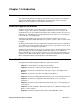
Chapter 1: Introduction Overview This chapter briefly describes the Digester Gas Monitor. This chapter also describes the Digester Gas Monitor Operator’s Manual (this document). Table 1 at the end of this chapter lists the specifications for the Digester Gas Monitor. About the Digester Gas Monitor The Digester Gas Monitor is a fixed-mounted, four channel gas monitor that detects methane, oxygen, carbon dioxide, and hydrogen sulfide.
• Chapter 10 describes the Digester Gas Monitor’s maintenance requirements and procedures. The Digester Gas Monitor Operator’s Manual uses the following conventions for notes, cautions, and warnings: NOTE: Describes additional or critical information. CAUTION: Describes potential damage to equipment. WARNING: ! ~ Describes potential danger that can result in injury or death.
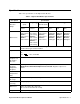
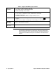
Specifications Table 1 lists specifications for the Digester Gas Monitor.
Table 1: Digester Gas Monitor Specifications Environmental Conditions • • • For indoor or outdoor locations (Type 4X) 0°C to 40°C (32°F to 104°F) max.
Chapter 2: Description Overview This chapter describes the Digester Gas Monitor’s external and internal components. External Description This section describes the housing and all external components of the Digester Gas Monitor. For the purposes of this description, the housing door is considered the front of the monitor.
• Silences the buzzer during an alarm 1, alarm 2, or alarm 3 condition if the alarm buzzer silence parameter in the Global Menu is set to CAN SILENCE BUZZER. See “Viewing and Changing Global Parameters” on page 47 for more information on setting the silence feature. • Silences and resets the optional horn/strobe during an alarm 1, alarm 2, or alarm 3 condition if the strobe alarm setting parameters are set to Resettable STROBE in the Configuration Menu.
Compressed Air Filter/Water Trap The compressed air filter/water trap is supplied with the Digester Gas Monitor to protect the Digester from impurities in the compressed air line. The filter is not factory installed and must be installed by the user. See “Making Fitting Connections” on page 28 for installation instructions. Aspirator/Sample Exhaust The aspirator/sample exhaust fitting is a hose barb fitting and is located just to the left of the conduit hubs. It accepts 1/4 inch ID flexible tubing.
8 • Internal Description Compressed Air Source Acropak Filter Oil Mist Filter Restrictor Check Valve Water Trap 2-Way Solenoid Valve D De-Energized: Normal Op. Energized: Blow Back Aspirator Compressed Regulator Air In Fitting 2-Way Solenoid Valve C De-Energized: Aspirator Off Energized: Aspirator On Compressed Air Filter/Water Trap, Field Installed Digester Sample Cal Gas Fitting 2-Way Solenoid Valve E De-Energized: Normal Op.
Horn/Strobe (Optional) Mounting Foot, 4X Main PCB Display PCB LCD Housing Mounting Plate Hydrophobic Filter Flow Switch Water Trap Flow Meter, Flow to Sensors, 0.6 - 5 SCFH Dryer Flow Meter, H2S Dilution Sample, .05 - .5 S CFH Solenoid Valve, 3 way Pressure Gauge Regulator Filter, Particle Check V alv e Flow Block withSensors Oil Mist Filter Aspirator, Air-Vac Solenoid Valve, 2 W ay, 3X Flow Meter, H2S Dilution Air, 0.2 - 2.
Display PCB The display PCB (printed circuit board) is mounted to the power supply mounting plate which is in turn mounted to the main PCB. The power supply mounting plate and main PCB are described below. The display PCB includes the LCD display, the LCD contrast adjust pot, the status LEDs, and the control switches. It is connected to the main PCB by the display cable which is a 20 conductor ribbon cable assembly.
either AC or DC power. • Fail LED The fail LED turns on when the Digester Gas Monitor is experiencing a fail condition, including a flow fail. See “Fail Condition” on page 44 and “Flow Fail Condition” on page 44 for a description of these conditions. • Alarm 1 LED The alarm 1 LED is on when the Digester Gas Monitor is experiencing an alarm 1 condition. • Alarm 2 LED The alarm 2 LED is on when the Digester Gas Monitor is experiencing an alarm 2 condition.
Main PCB This section describes the components of the main PCB. Strobe Terminal Strip Termination Jumper Main PCB Control PCB AC In Terminal Strip Detector/ Transmitter Terminal Strips Common/ Channel Alarm Terminal Strip Controller Terminal Strip Channel A larm Terminal Strip Ground Stud Figure 5: Main PCB Component Location Terminal Strips The Digester Gas Monitor includes 9 terminal strips for wiring connections. See “Wiring the Digester Gas Monitor” on page 23 for detailed wiring procedures.
main PCB (see Figure 5 on page 12). These four 11-point terminal strips facilitate wiring connections to the detectors. They also provide terminals to connect a recording device to a 4 to 20 mA output for each channel. The top terminal strip is for channel 1 connections and each subsequent strip is used for the next channel with the bottom terminal strip being for channel 4 connections. The Digester Gas Monitor detectors are factory wired to the terminal strips.
• AC Terminal Strip The 3-point AC terminal strip is located above the controller terminal strip (see Figure 5 on page 12). The AC terminal strip facilitates wiring connections to the AC power source. Relays The Digester Gas Monitor includes eight channel relays and one common fail relay. It also includes four common/channel relays which are factory set for operational use of the Digester Gas Monitor.
page 68 for instructions to use the Digester Gas Monitor in a Modbus system. Ground Stud The threaded ground stud is used for making connections to earth ground. It is located in the lower right corner of the main PCB and is connected through the main PCB to the G (ground) terminal on the AC terminal strip. It is also connected to each conduit hub with a wire. A kep nut on the stud may be removed for installation of one or more user supplied lugs to make wiring connections to earth ground.
sensors are retained in the flow block by brackets. The H2S sensor is retained by the Oring compression force of the O-rings it is inserted past. When viewed from the front of the Digester Gas Monitor, the methane sensor is in the front right corner, the H2S sensor is in the front left corner, the oxygen sensor is in the back right corner, and the CO2 sensor is in the back left corner. Sensors Infrared Methane (CH4) Sensor The IR CH4 sensor is an infrared type plug-in detector.
appropriate flow rate depends on the full scale range of the H2S sensor. See “Adjusting the Flow Rates” on page 33 for more information. H2S Dilution Air Flowmeter The H2S Dilution Air flowmeter is located in the middle right of the Digester Gas Monitor’s flow system and indicates the fresh air flow rate to the H2S sensor. The appropriate flow rate depends on the full scale range of the H2S sensor. See “Adjusting the Flow Rates” on page 33 for more information.
Factory Wiring The figure below shows the factory wiring. Standard channel assignment is shown. If your Digester Gas Monitor has less than four sensors, your detector wiring will be slightly different.
Optional Horn/Strobe This section describes the optional horn/strobe available for the Digester Gas Monitor. It can be ordered with the Digester Gas Monitor or it can be ordered at a later date and be field installed. The horn/strobe is wired to the Strobe Terminal Strip as shown in Figure 8 and Figure 9 below. NOTE: If the Digester Gas Monitor is not ordered with a horn/strobe, the hole that is intended for use with the horn/strobe will be plugged and the receptacle will not be installed.
Configuration Menu” on page 51). NOTE: See “Chapter 3: Installation and Start Up” on page 22 for complete Digester Gas Monitor installation instructions. CAUTION: Do not adjust the strobe brightness or the horn volume at the horn/strobe, as this may overload the Digester Gas Monitor strobe control circuit. Even if the horn/strobe is ordered at the same time as the Digester Gas Monitor, the horn/ strobe does not come factory installed to the Digester Gas Monitor. To install the horn/ strobe: 1.
7. Connect the plug coming from the horn/strobe to the receptacle coming from the strobe terminal strip. 6.81 5.97 4.83 6.
Chapter 3: Installation and Start Up Overview This chapter describes procedures to mount the Digester Gas Monitor, make wiring connections to the monitor, and start up the monitor. WARNING: Perform all installation and start-up procedures in a known fresh air environment, an environment free of combustible and toxic gasses and of normal oxygen content. The Digester Gas Monitor is not in operation as a gas monitoring device until the start up procedure is complete.
4. Prepare the selected mounting site as required to mount the Digester Gas Monitor. It should be mounted at eye level (4 1/2 to 5 feet from the floor). Refer to Figure 11 for the outline and mounting dimensions. 5. Position the monitor on the vertical mounting surface. Use a level to ensure that the Digester Gas Monitor housing is level in all planes. The flowmeters will not operate properly if the Digester Gas Monitor is not mounted as shown below and level in all planes. 6. Insert 1/2 in.
Figure 12: Digester Gas Monitor External Wiring Diagram 24 • Wiring the Digester Gas Monitor Digester Gas Monitor Operator’s Manual Bla ck R ed S AM P W G OX Y W G B 4-2 0 m A OU TP U T C NO NC NO NC C R EL AY -B NO NC C R EL AY -C C R EL AY -D NO NC For Factory Use Only C R EL AY -A NO NC NO NC Relay Contac ts Rated F or 1 0 A mps A t 2 50 V AC C CH 4 R EL AY -2 C NO NC CH 4 R EL AY -1 C NO NC CH 3 R EL AY -2 C NO NC CH 3 R EL AY -1 C NO NC CH 2 R EL AY -2 C NO NC CH 2
Connecting the AC Power Source NOTE: If you are using DC power as the primary power source, go to the next section, “Connecting the DC Power Source”. The AC in terminal strip will accept 24 - 14 AWG wire. When selecting wire to connect the AC power source to the Digester Gas Monitor, be sure to meet the local electrical code. Also be sure to use an appropriate circuit breaker in the AC line close to the Digester Gas Monitor that meets the local electrical code.
page 39 for a complete description of this feature and what type of battery to use. If DC power is the primary power source, DO NOT connect AC power. 1. Turn off or unplug all incoming power to the Digester Gas Monitor. 2. Open the housing door, then place the power switch in the OFF position. CAUTION: The power switch does not control DC input power. 3. Locate the DC input power terminals on the controller terminal strip near the lower right edge of the main PCB (see Figure 5 on page 12).
2. Open the housing door, then place the power switch in the OFF position. CAUTION: The power switch does not control DC input power. 3. Locate the applicable alarm terminal strip (see Figure 5 on page 12). 4. Install an appropriately rated cable bushing or conduit in an unused conduit hub on the bottom of the Digester Gas Monitor. 5. Guide the wiring of the external alarm device through the selected conduit hub on the bottom of the Digester Gas Monitor housing. 6.
6. Connect the leads from the recording device to the recorder output terminals of the selected active channels as shown in Figure 16 below.
Table 4: Compression Fitting Maximum Tubing Lengths Maximum Tubing Length (ft.) Fitting Compressed Air Inlet Determine length based on installation Recommended Tubing Size 1/4 inch OD tubing rated for pressure supplied Recommended Tubing Material Stainless steel, copper, or aluminum * It is not necessary to route the dryer exhaust away from the digester, but it may be done if desired. Compressed Air Inlet Fitting and Compressed Air Filter/Water Trap 1.
4. Before tightening the nut, be sure to hold the fitting still from the outside so it does not rotate using a 5/8 inch open-end wrench or an adjustable wrench (see Figure 17). While holding the fitting still, firmly tighten the nut with a 9/16 inch open-end wrench or an adjustable wrench so the ferrules crimp onto the sample tubing and make a seal. 5. Connect the other end of the tubing coming from the compressed air inlet fitting to the filter/water trap exhaust.
Fresh Air Inlet, Dryer Exhaust, and Digester Sample Inlet Fittings 1. Install the desired length of 1/4 inch OD rigid metal or rigid plastic tube into the tube nut and ferrules as shown in the figure below. Stainless steel, Teflon, or polypropylene tubing is recommended.
WARNING: The aspirator/sample exhaust may contain high levels of toxic gases. It is important to route the exhaust to a fresh air area where there is no danger of it being inhaled. Starting Up the Digester Gas Monitor Perform the following procedure to place the Digester Gas Monitor into normal operation. NOTE: The following screens illustrate a four-channel Digester Gas Monitor. Depending on what version of the Digester Gas Monitor you have, your screens may appear slightly different. 1.
8. Any unused channels are configured as NOT USED in the Configuration Menu at the factory. For any unused channels, NOT USED is displayed on the line for that channel. If any channels have been configured as STANDBY in the Configuration Menu, STANDBY is displayed on the line for that channel. See “Viewing and Changing Channel Parameters” on page 51 for a description of the NOT USED and STANDBY configurations. 9. Verify that the PILOT light is on.
Table 5: Flow Rates for Different H2S Ranges H2S Range Flow to Sensors Flowmeter H2S Dilution Sample Flowmeter H2S Dilution Air Flowmeter 0 - 1000 ppm 3.0 SCFH 0.3 SCFH 1.0 SCFH 0 - 3000 ppm 3.0 SCFH 0.25 SCFH 1.2 SCFH 0 - 5000 ppm 3.0 SCFH 0.2 SCFH 1.4 SCFH 1. Use the regulator in the bottom left corner of the Digester Gas Monitor to adjust the Flow to Sensors flowmeter in the upper right corner to 3.0 SCFH. 2.
Chapter 4: Operation Overview This chapter describes the Digester Gas Monitor in normal operation. This chapter also describes the Digester Gas Monitor in alarm 1, alarm 2, alarm 3, and fail conditions, and suggests responses to these conditions. Normal Operation Normal operation is defined as follows: • the start-up procedure is complete. • the Digester Gas Monitor is not indicating an alarm 1, alarm 2, alarm 3, or fail condition.
NOTE: If a forced detection cycle overlaps the start time of a scheduled detection cycle, that scheduled detection cycle will begin immediately after the forced detection cycle is complete. The next scheduled detection cycle will occur on schedule.
5. The H2S reading is taken after 90 seconds. The solenoids will click and the flow to the sensors will be stopped for 15 seconds to allow for a stabilization period. The countdown will continue on the display. Sampling 0 Min 14 Seconds 6. At the end of the stabilization period, the methane, oxygen, and carbon dioxide readings will be taken. The gas readings for all channels will then be displayed for 5 seconds. 1: METHANE 2: OXYGEN 3: CO2 4: H2S 34 %LEL 0.9 %VOL 15.3 %VOL 678 ppm 7.
4 - 20 mA Signal Output Operation The output at the recorder output terminals on the detector/transmitter terminal strip for each channel is a 4 - 20 mA signal that corresponds to the detection range of the Digester Gas Monitor. It behaves as follows: • During the Digester Gas Monitor’s initial 1 minute warm-up period and 1 minute standby period after being turned on, the signal output will be fixed at 3.5 mA.
3. After the minimum and maximum readings have been displayed for about ten seconds, the following screen appears for about seven seconds. Push Reset Again To Reset Min/Max Values Or Wait To Return To Normal Operation • To reset the minimum and maximum readings, before the unit returns to Standby Mode press and release the reset switch button. The display indicates Min/Max Values Have Been Reset and the monitor will then return to Standby Mode.
NOTE: The Digester Gas Monitor’s alarms are factory set in such a way that it is unlikely that an alarm condition will be encountered but the Digester Gas Monitor allows the configuration of various alarm and alarm relay parameters. The description of alarm indications below assumes that all parameters are at their factory set values. It also assumes that the alarm setpoints are set such that alarm 1< alarm 2 < alarm 3 and all alarms are increasing.
Table 6: Visual and Audible Alarm Indications Condition Fail Cause • Disconnected or misconnected detector wiring Display reading below -10% of full scale or lower Malfunctioning components • • Flow Fail Flow to system falls below 1.6 SCFH Visual Indication(s) • • Fail LED is on FAIL message replaces the gas reading • If installed and set to activate for fail, horn/strobe flashes NOTE: There is a 30 second delay on the fail indications.
Responding to an Alarm 1 Condition This section suggests the following responses to an alarm 1 condition: 1. Follow your established procedure for a low-level combustible or toxic gas condition or an increasing oxygen condition. 2. An alarm condition can be acknowledged at any point during the detection cycle or during Standby Mode. To acknowledge the alarm condition and silence the buzzer while in an alarm 1 condition, press and release the reset switch.
begin to flash indicating the alarm condition has been acknowledged. You cannot deenergize the alarm 2 relays until the gas reading falls below the alarm 2 setpoint. 3. Alarms are factory set as latching. After the gas reading falls below the alarm 2 setpoint during a detection cycle, press and release the reset switch to reset the alarm circuit.
NOTE: The Digester Gas Monitor saves the last gas reading taken during the sample period of a detection cycle. If the gas reading is still above the alarm 1 setpoint at the end of the sampling period, that gas reading is saved and the alarm 1 circuit cannot be reset. The reading must fall below the alarm 1 setpoint during the sampling period of a detection cycle before the alarm 1 circuit can be reset.
• the common fail relay de-energizes; • the flow to the sensors is stopped; • After the purge is completed, a sample sequence is initiated. If the low flow condition recurs during this sample period, the Digester Gas Monitor will stop sampling and wait for user intervention. Responding to a Flow Fail Condition This section suggests responses to a flow fail condition. 1.
Gas Monitor, then connect a 24 VDC battery. 2. Determine and correct the cause of primary DC power loss. When the DC power source rises above 19.0 volts, the Digester Gas Monitor begins the warm up process. 3. Verify that the Digester Gas Monitor enters normal operation after its warm-up sequence. • If DC power is the backup power source: 1. If a non-rechargeable battery is used for backup, replace the battery. 2. Determine and correct the cause of primary AC power loss.
Chapter 5: Global Menu Overview This chapter describes how to view and change Digester Gas Monitor instrument parameters using the Global Menu. The global parameters are the cycle interval time setting, the optional horn/strobe’s installation setting, the relay normal state setting, the alarm buzzer silence setting, and the fail silence setting. The Global Menu is accessed using the ESCAPE and UP/YES control switches. The Global Menu includes a 5-minute timeout feature.
2. Press and release the UP/YES button to continue in the Global Menu to the Cycle Interval Time screen. Cycle Interval Time: 1 HOUR UP / DN then ENT / ESC 3. Use the UP/YES and DOWN/NO buttons to set the cycle interval time. It can be set to 15 minutes, 1 hour, 4 hours, 8 hours, or 24 hours. 4. Press ENTER to save the changes and continue to the STROBE Installation screen. STROBE Installation: STROBE IS INSTALLED UP / DN then ENT / ESC 5.
11. Press ENTER to save the changes and continue to the Fail Silence screen. Press the ESCAPE button to go back to the Alarm Buzzer Silence Screen. FAIL SILENCE: CAN SILENCE FAIL UP / DN then ENT / ESC 12. Use the UP/YES and DOWN/NO buttons to toggle between CAN SILENCE FAIL and CAN’T SILENCE FAIL. 13. Press ENTER to save the changes and move to the Save Settings screen. Press ESCAPE to go back to the ALARM BUZZ SILENCE screen. Save Settings? [Y / N] [ESCAPE] to back up 14.
Table 7: Global Menu Parameters (Continued) Global Parameter (Factory-Set Value) NORMAL RELAY STATES (NORM DE-ENERGIZED) Description If set to NORM DE-ENERGIZED, the gas alarm relays are de-energized in normal operation and energize when the appropriate alarm circuit is activated. The NO (normally open) relay contacts are open during non-alarm operation and close when the appropriate alarm condition occurs.
Chapter 6: Configuration Menu Overview This chapter describes how to view and change Digester Gas Monitor channel parameters including alarm point settings and channel relay settings using the Configuration Menu. The Configuration Menu is accessed using the ESCAPE and ENTER control switches. The Configuration Menu includes a 5-minute timeout feature. If you do not press a control switch for 5 minutes, the Digester Gas Monitor automatically returns to Standby Mode.
2. Press and release the UP/YES button to continue in the Configuration Menu to the Select Channel Screen. Select Channel 1 UP / DN then ENT / ESC 3. Use the UP/YES or DOWN/NO buttons to select the channel whose parameters you want to view and/or update, then press and release the ENTER button. The first channel parameter screen appears and it allows you to select whether the channel is set to ACTIVE, STANDBY, or, NOT USED. CHANNEL: 1 ACTIVE UP / DN then ENT / ESC 4.
DOWN/NO button. The display will indicate that no settings have been changed for a few seconds and the channel parameters will return to their original settings. 9. The following screen will appear asking if you want to configure more channels. Do You Want To Do More Channels? [Y / N] If yes, press and release the UP/YES button to return to the Select Channel Screen. Begin at step 3 above to configure another channel. If no, then press the DOWN /NO button to return to Standby Mode.
Table 8: Configuration Menu Parameters (Continued) Channel Parameter (Factory-Set Value) Description Alarm-1 Latching (LATCHING) If set as LATCHING, you must press the RESET button to reset the alarm 1 circuit after the alarm 1 condition passes. If set as SELF-RESETTING, the Digester Gas Monitor automatically resets the alarm 1 circuit after the alarm 1 condition passes.
Table 8: Configuration Menu Parameters (Continued) Channel Parameter (Factory-Set Value) ALM-2 STROBE Setting (NonResettable STROBE) Description If set to Resettable STROBE, the strobe can be turned off with the Reset Switch while an alarm 2 condition still exists. If set to NonResettable STROBE, the strobe cannot be turned off with the Reset Switch while an alarm 2 condition still exists. If set to NO STROBE, the strobe will not activate due to an alarm 2 condition.
Table 8: Configuration Menu Parameters (Continued) Channel Parameter (Factory-Set Value) Description Relay-1 Assignment (ALARM-1) The alarm condition that activates relay 1. It can be set for activation by the following alarm conditions: • ALARM-1 • ALARM-2 • ALARM-3 • ALARMS 1 or 2 • ALARMS 1 or 3 • ALARMS 2 or 3 • ALARMS 1, 2, or 3 • Use As Channel FAIL (If you choose this setting, the relay is normally energized) Relay-2 Assignment (ALARM-2) The alarm condition that activates relay 2.
Chapter 7: Input Setup Menu Overview This chapter describes how to use the Input Setup Menu to select each channel’s detector input type and the gas setup. The detector input type determines whether a direct connect type or a 4 - 20 mA type of detector will be used and the gas setup determines the target gas, detection units, and the detection range full scale. The Input Setup Menu is accessed using the ENTER control switch when powering up the Digester Gas Monitor.
scroll through the choices and then press and release the ENTER button to accept the selection. The INPUT Type screen will appear. In the example below, channels 1 has been selected for setup. CHANNEL(S): 1 INPUT Type RWGB Direct UP / DN then ENT / ESC 5. Use the UP/YES or DOWN/NO button to scroll through the choices of input types. Table 9 below lists the choices of input type for the Digester Gas Monitor.
• If you select the oxygen direct input type, the Save Settings? screen will appear. Proceed to step 11. 7. Use UP/YES or DOWN/NO button to scroll through the gas setup choices. There are several choices whose gas name, full scale, and detection units are predefined. For these choices, the gas name, full scale, and detection units are displayed. There is also one choice named CUSTOM that allows you to enter the gas name, full scale, and detection units. 8.
• Use the UP/YES or DOWN/NO button to scroll through the units choices. When the desired units are displayed, press and release the ENTER button. The Full Scale Readout screen appears. CHANNEL(S): 1 Full Scale Readout 100 %LEL UP / DN then ENT / ESC • USE the UP/YES or DOWN/NO button to scroll through the available choices for the full scale setting. When the desired full scale setting is displayed, press and release the ENTER button. 10. The Save Settings? screen appears. Save Settings? [Y / N] 11.
Chapter 8: Calibration Mode Overview This chapter describes how to calibrate the Digester Gas Monitor’s active channels using Calibration Mode. In Calibration Mode, you can: • Set the calibration timeout. • Perform a fresh air adjust on selected channels. • Perform a gas adjust on selected channels. • View Max Spans. Table 10 below briefly describes the four operations that can be performed in Calibration Mode. A more detailed description of each operation is given later in this chapter.
Entering Calibration Mode WARNING: The Digester Gas Monitor is not an active gas monitoring device during the calibration procedure. When you enter Calibration Mode, the 4-20 mA output signal will “freeze” at 3.5 mA for each active channel, all relays and alarm LEDs will remain in their current state at the time that you entered Calibration Mode, and the alarm buzzer and strobe will turn off if they were activated until you exit Calibration Mode.
2. With SET CAL TIMEOUT displayed, press and release the ENTER button. The Calibration Timeout Screen appears. Calibration Timeout 15 minutes UP / DN then ENT / ESC 3. Use the UP/YES or DOWN/NO button to adjust the calibration timeout to the desired setting. The calibration timeout can be set from 5 minutes to 240 minutes (4 hours) in 5 minute increments. The factory set calibration timeout is 15 minutes. 4. If you want to save the displayed calibration timeout setting, press and release the ENTER button.
Performing a Fresh Air Adjustment Performing a fresh air adjustment sets the gas reading in fresh air for the selected channels to zero for all channel types except oxygen. The oxygen channel is set to 20.9% in fresh air. To perform a fresh air adjustment for the selected channels, do the following: 1. Navigate to the Select Operation Screen as described in “Entering Calibration Mode” on page 62. 2. Use the UP/YES or DOWN/NO button to display PERFORM AIR ADJUST on the Select Operation Screen.
11. If you want to perform a gas adjustment to complete the calibration, proceed to the next section, “Performing a Gas Adjustment”. If you do not want to perform a gas adjustment, use the UP/YES and DOWN/NO buttons to scroll to EXIT CAL MENU. Press and release the ENTER button to exit Calibration Mode and return to Standby Mode. Performing a Gas Adjustment Performing a gas adjustment sets the response level to calibration gas for the selected channels. This is also known as a span adjustment.
9. Repeat step 8 for each selected channel. When the last selected channel’s calibration gas concentration has been accepted, the Digester Gas Monitor will begin to draw sample through the Calibration Gas Fitting. The two screens shown below will alternate. Apply CAL GAS To Gas Detectors - > ENTER when Done - > ESCAPE to Abort 1: METHANE 2: OXYGEN 3: CO2 49 %VOL 12.0 %VOL 15.3 %VOL 10. Connect the tubing from the demand flow regulator to the Calibration Gas Fitting.
the detector was exposed to 50 %LEL gas. If the maximum span value is close to the calibration gas value, for example if it is 53 %LEL for a 0 - 100 %LEL channel when 50 %LEL calibration gas is used, the sensor should be replaced soon. To make the maximum span values as meaningful as possible, there is a limit to how much remaining adjustment the screen will indicate.
Chapter 9: RS-485 Modbus Output Overview This chapter describes the Digester Gas Monitor’s RS-485 Modbus output and how to configure the Digester Gas Monitor to make use of it. It also discusses how to wire the Digester Gas Monitor into a Modbus system. The Digester Gas Monitor provides an RS-485 serial communications interface. It is a Modbus Slave Device, supporting 2-wire RS-485 Modbus RTU serial communications.
Recommended Modbus Wiring The recommended Modbus wiring for the Digester Gas Monitor is illustrated in Figure 20 below.
ID=1 ID=32 Digester Gas Analyzer Termination Jumper Installed Digester Gas A nalyzer Termination Jumper Installed Modbus Master RS-485 RS-485 Digester Gas Analyzer Termination Jumper Not Installed Digester Gas Analyzer Termination Jumper Not Installed Digester Gas A nalyzer Termination Jumper Not Installed Digester Gas A nalyzer Termination Jumper Not Installed ID=2 ID=3 ID=4 ID=31 Up to 32 Digester Gas A nalyzers can be connected without a repeater Figure 22: Multiple Digester Gas Monitors
2. Press and release the UP/YES button to continue in the Modbus Menu to the Modbus Feature Enable/Disable screen. MODBUS Feature is: DISABLED UP / DN then ENT / ESC 3. In the parameter screens, use the ENTER button to accept a displayed parameter setting and proceed to the next parameter or the ESCAPE button to backup a screen. 4.
Table 12: Modbus Configuration Parameters (Continued) Modbus Mode Parameter Response Delay Available Settings & Description The response delay can be set from 0 (factory setting) to 20 mS. This is an optional additional delay inserted by the Digester Gas Monitor prior to returning a response message to the Master. It may be helpful in some installations where the Master’s preparedness to receive responses might be delayed.
Registers 40002 - 40015, Channel 1 Information Register 40002 Table 14 below shows the information in register 40002.
Registers 40014 - 40015 The 4 bytes (characters) in registers 40014 and 40015 contain the channel gas units in ASCII characters. Registers 40016 - 40029, Channel 2 Information Register 40016 Table 16 below shows the information in register 40016.
Registers 40025 - 40027 The 6 bytes (characters) in these registers contain the channel gas reading in ASCII characters. Registers 40028 - 40029 The 4 bytes (characters) in registers 40028 and 40029 represent the channel gas units in ASCII characters. Registers 40030 - 40043, Channel 3 Information Register 40030 Table 18 below shows the information in register 40030.
Registers 40035 - 40038 The 8 bytes (characters) in these registers contain the channel gas name in ASCII characters. Registers 40039 - 40041 The 6 bytes (characters) in these registers contain the channel gas reading in ASCII characters. Registers 40042 - 40043 The 4 bytes (characters) in registers 40042 and 40043 contain the channel gas units in ASCII characters. Registers 40044 - 40057, Channel 4 Information Register 40044 Table 20 below shows the information in register 40044.
Register 40048 Table 21 below shows the information in register 40048. Table 21: Register 40048 Channel Reading Sign (+/-) (MS-Byte) • • 0 = Positive (+) 1 = Negative (-) Channel Decimal Point Position (LS-Byte) • • • • 0 = No Decimal Point 1 = .x 2 = .xx 3 = .xxx Registers 40049 - 40052 The 8 bytes (characters) in these registers contain the channel gas name in ASCII characters. Registers 40053 - 40055 The 6 bytes (characters) in these registers contain the channel gas reading in ASCII characters.
Chapter 10: Maintenance Overview This chapter describes preventive maintenance procedures for the Digester Gas Monitor and replacement procedures for the sensors, the air filter, the hydrophobic filter, the oil mist filter, the water trap filter element, and the AC fuses. It includes a troubleshooting guide for problems you may encounter with the Digester Gas Monitor.
Troubleshooting Table 22 describes symptoms, probable causes, and recommended actions for the most common problems you may encounter with the Digester Gas Monitor. Table 22: Troubleshooting the Digester Gas Monitor Condition No Power to Instrument and/or Display PCB Symptom(s) • • The PILOT light is off. The display screen is blank. Probable Causes • • • Frequent or Suspect Alarms • • Momentarily Unstable Gas Readings on Display • The Digester Gas Monitor alerts you to frequent or suspect alarms.
Table 22: Troubleshooting the Digester Gas Monitor (Continued) Condition Buzzer or Optional Horn/Strobe Not Working Symptom(s) • • Reset Switch not Working • • 80 • Troubleshooting Probable Causes The buzzer or horn/strobe does not sound an audible alarm during alarm conditions. The buzzer or horn/strobe sounds weak or broken. • Depending on the instrument setup, the buzzer or strobe does not turn off in the appropriate situation when the reset switch is pressed.
Table 22: Troubleshooting the Digester Gas Monitor (Continued) Condition Flow Fail or Low Flow Symptom(s) • • • The Digester Gas Monitor indicates a flow failure alarm. The Flow to Sensors flowmeter cannot be set to 3.0 SCFH. The H2S Dilution flowmeters cannot be set to their appropriate flows. Probable Causes • • • • • • • • Water Condensation in Flow System • A visual inspection reveals condensation in the flow system.
Sensor Replacement This section describes how to replace the sensors in the Digester Gas Monitor. The figure below shows the flow block that is installed in the Digester Gas Monitor and the location of each sensor in the flow block. Oxygen Sensor CO2 Sensor Methane Sensor Front of Flow Block W hen Viewed From Front of Digester H2S Sensor Figure 23: Flow Block Replacing the Methane Sensor 1. Turn off the Digester Gas Monitor 2. Turn off incoming power to the Digester Gas Monitor. 3.
9. Reinstall the preamp circuit board with the sensor onto the flow block. 10. Turn the regulator knob clockwise to set the sensor flow to 3 SCFH when you restart the system. 11. Turn on incoming power. 12. Calibrate the replacement sensor as described in “Performing a Calibration” on page 63. Replacing the Oxygen Sensor 1. Turn off the Digester Gas Monitor. 2. Turn off incoming power to the Digester Gas Monitor. 3. Open the housing door of the Digester Gas Monitor. 4.
9. Reinstall the preamp circuit board with the sensor onto the flow block. 10. Turn the regulator knob clockwise to set the sensor flow to 3 SCFH when you restart the system. 11. Turn on incoming power. 12. Calibrate the replacement sensor as described in “Performing a Calibration” on page 63. Replacing the CO2 Sensor 1. Turn off the Digester Gas Monitor. 2. Turn off incoming power to the Digester Gas Monitor. 3. Open the housing door of the Digester Gas Monitor. 4.
the system. Replacing the Hydrophobic Filter This section describes how to replace the hydrophobic filter. 1. Turn off the Digester Gas Monitor. 2. Turn off or unplug power to the Digester Gas Monitor. 3. Open the housing door of the Digester Gas Monitor. 4. Turn the regulator knob all the way counterclockwise to close the regulator output. 5. Locate the hydrophobic filter. It is just to the left of the main circuit board. 6. Grasp the hydrophobic filter and pull it out of its metal clamp. 7.
Replacing the Oil Mist Filter 1. Turn off the Digester Gas Monitor. 2. Turn off or unplug power to the Digester Gas Monitor. 3. Open the housing door of the Digester Gas Monitor. 4. Turn the regulator knob all the way counterclockwise to close the regulator output. 5. Locate the oil mist filter. It is located along the middle bottom of the flow assembly. 6.
Filter with Fittings Attached Push FLOW FLOW 9. Use needle nose pliers to press down on the collet of each connected push fitting and remove the fittings from the oil mist filter. Discard the old oil mist filter but be sure to keep the push fittings that were removed. Filter with Fittings Detached Figure 25: Removing the Fittings from the Oil Mist Filter 10. Press the white, right angle push fitting onto the new oil mist filter’s barb that has the arrow pointing toward it. 11.
5. Locate the water trap. It is located along the middle left of the flow assembly. 6. The fitting at the bottom of the water trap has a nut and a hex. The hex is positioned above the nut. Use a 9/16 inch open-end wrench or an adjustable wrench to hold the hex in place. Use a second 9/16 inch open-end wrench of adjustable wrench to unscrew the nut. The line leading to the bottom of the water trap includes flexible tubing. Once the nut is loose, move the nut and tubing out of the way.
it in the socket. 7. Plug in or turn on all incoming power to the Digester Gas Monitor. 8. Place the Digester Gas Monitor’s power switch in the ON position, then verify that the PILOT light is on. 9. Close and secure the housing door. Parts List Table 23 lists the part numbers and descriptions for replacement parts and accessories offered for the Digester Gas Monitor. Table 23: Parts List, Digester Gas Monitor Part No. Description 06-1248RK Sample tubing (3/16 in. x 5/16 in.
Table 23: Parts List, Digester Gas Monitor Part No.