
Instruction Manual

Beacon 410 Gas Monitor Operator’s Manual Supported Modbus Functions • 59
Registers 40002 - 40015, Channel 1 Information
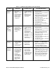
Register 40002
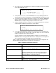
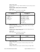
Table 13 below shows the information in register 40002.
Registers 40003 & 40004
The 32 bits in registers 40003 and 40004 contain the channel 1 numerical reading in
single precision floating point IEEE format.
Register 40005
The 16 bits in register 40005 contain the channel 1 numerical reading in integer form
omitting the sign (+ or -) and the decimal point.
Register 40006
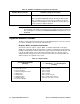
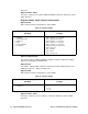
Table 14 below shows the information in register 40006.
Registers 40007 - 40010
The 8 bytes (characters) in these registers contain the channel gas name in ASCII
characters.
Registers 40011 - 40013
The 6 bytes (characters) in these registers contain the channel gas reading in ASCII
characters.
Registers 40014 - 40015
The 4 bytes (characters) in registers 40014 and 40015 contain the channel gas units in
Table 13: Register 40002
Channel Operational State
(MS-Byte)
Channel Status Bits
(LS-Byte)
• 0 = (this code is not used)
• 1 = Standby
• 2 = Normal Operation
•3 = Warm Up
•4 = Fail
• 5 = Post-Calibration
•6 = Low Power
• Bit-7 (msb) = Relay-1 (1 = energized)
• Bit-6 = Relay-2 (1 = energized)
• Bit-5 = (this bit is not used)
• Bit-4 = Alarm-1 (1 = asserted)
• Bit-3 = Alarm-2 (1 = asserted)
• Bit-2 = Alarm-3 (1 = asserted)
• Bits[1:0] = Channel Usage Code
[00] = Not Used
[01] = Standby
[10] = Active
[11] = unused code
Table 14: Register 40006
Channel Reading Sign (+/-)
(MS-Byte)
Channel Decimal Point Position
(LS-Byte)
• 0 = Positive (+)
• 1 = Negative (-)
• 0 = No Decimal Point
• 1 = .x
• 2 = .xx
• 3 = .xxx