Combustible Gas and Hydrogen Sulfide Beacon 200 Rig Monitor Operator’s Manual Part Number: 71-0243RK Revision: B Released: 9/30/14 www.rkiinstruments.
WARNING Read and understand this instruction manual before operating instrument. Improper use of the rig monitor could result in bodily harm or death. Periodic calibration and maintenance of the rig monitor is essential for proper operation and correct readings. Please calibrate and maintain this rig monitor regularly! Frequency of calibration depends upon the type of use you have and the sensor types.
Product Warranty RKI Instruments, Inc. warrants gas alarm equipment sold by us to be free from defects in materials, workmanship, and performance for a period of one year from date of shipment from RKI Instruments, Inc. Any parts found defective within that period will be repaired or replaced, at our option, free of charge.
Table of Contents Chapter 1: Introduction . . . . . . . . . . . . . . . . . . . . . . . . . . . . . . . . . . . . . . . . . . . . . . . . . 1 Overview . . . . . . . . . . . . . . . . . . . . . . . . . . . . . . . . . . . . . . . . . . . . . . . . . . . . . . . . 1 About the Beacon 200 Gas Monitor . . . . . . . . . . . . . . . . . . . . . . . . . . . . . . . . . . . 1 About this Manual . . . . . . . . . . . . . . . . . . . . . . . . . . . . . . . . . . . . . . . . . . . . . . . . . 2 Specifications . . . . .
Chapter 6: Maintenance . . . . . . . . . . . . . . . . . . . . . . . . . . . . . . . . . . . . . . . . . . . . . . . 33 Overview . . . . . . . . . . . . . . . . . . . . . . . . . . . . . . . . . . . . . . . . . . . . . . . . . . . . . . . 33 Calibration Program . . . . . . . . . . . . . . . . . . . . . . . . . . . . . . . . . . . . . . . . . . . . . . 33 Adjusting Strobe/Horn Volume . . . . . . . . . . . . . . . . . . . . . . . . . . . . . . . . . . . . . . 39 Replacing Components of the Rig Monitor . . . .
Chapter 1: Introduction Overview This chapter briefly describes the Beacon 200 Rig Monitor. This chapter also describes the Beacon 200 Rig Monitor Operator’s Manual (this document). Table 1 at the end of this chapter lists the specifications for the Beacon 200 Rig Monitor. About the Beacon 200 Rig Monitor The Beacon 200 Rig Monitor is a fixed-mounted, continuous-monitoring gas detection instrument. This gas monitor is capable of detecting gas at two locations.
About this Manual The Beacon 200 Gas Monitor Operator’s Manual uses the following conventions for notes, cautions, and warnings. NOTE: Describes additional or critical information. CAUTION: Describes potential damage to equipment. WARNING: Describes potential danger that can result in injury or death.
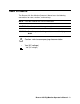
Specifications Table 1 lists specifications for the Beacon 200 Rig Monitor. Table 1: Beacon 200 Rig Monitor Specifications Description Specification Input Power 10.8 - 14.5 VDC, 1.2A VDC Construction (housing) Fiberglass/polyester with lexan window (NEMA 4X) Controller Dimensions 21.0 in. H x 8.5 in. W x 7.00 in. D (533 mm H x 216 mm W x 178 mm D) Weight 20 lbs. Environmental Conditions • • -20°C to 50°C (-4°F to 122°F) max.
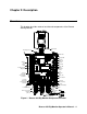
Chapter 2: Description Overview This chapter describes external and internal components of the Beacon 200 Rig Monitor.
External Description This section describes the housing and all external components of the Beacon 200 Rig Monitor. For the purposes of this description, the housing door is considered the front of the monitor. Housing The Rig Monitor’s fiberglass housing is weather- and corrosion-resistant. It is suitable for installation where general purpose equipment is in use. The housing door is hinged on the left side and is secured by two latches on the right side.
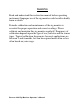
LEL Detector Junction Box and Cable The LEL detector consists of a junction box with a mounting bracket, the detector, and the calibration cup/splash guard. Mounting Bracket To Beacon 200 Cable Bushing Terminal Strip LEL Detector (Factory Wired) Calibration Cup/With Diffusion Holes Figure 2. LEL Junction Box Component Location The LEL detector is factory wired through the left cable bushing of the Beacon 200 and has a 25 foot cable for remote installation.
to the interior of the junction box. The combustible gas detector is a catalytic type detector that produces an electrical output that corresponds to the detection range. It is packaged in a 1/2 inch NPT nipple with a sintered metal flame arrestor on one end allowing ambient air to diffuse into the detector. The flame arrestor also contains any sparks which may occur within the detector. The calibration cup/splash guard is screwed onto the bottom of the detector.
The H2S detector is factory wired through the middle cable bushing of the Beacon 200 and has a 25 foot cable for remote installation. The mounting bracket at the top of each junction box is used to mount the junction box. The junction box protects the detector wiring connections. Three spacers installed on the back of the junction box control the distance of the junction box from a mounting surface and ensure that there is enough room to perform a calibration.
12 VDC Battery Cable A 50 foot cable with clamps for connection to a 12 VDC battery (customer supplied battery not included) is factory-wired through the right cable bushing of the Beacon 200. One end of the cable is connected to the DC In terminal strip. Internal Description This section describes the internal components of the Rig Monitor. Display Printed Circuit Board (PCB) The display PCB is mounted to the power supply mounting plate which is in turn mounted to the main PCB.
Status Lights The Rig Monitor includes four status lights that indicate the current status of the monitor. The status lights are to the left and right of the display (see Figure 5). • Pilot Light. The pilot light is on when the Rig Monitor is receiving incoming power. • Fail Light. The fail light turns on when the Rig Monitor is experiencing a fail condition. A fail condition can be caused by a failure within the Rig Monitor or detector head(s) wired to the Rig Monitor.
Main PCB The main PCB is mounted inside the housing. The power supply mounting plate is mounted to the main PCB with four standoffs and the display PCB is mounted to the power supply mounting plate with four standoffs. The main PCB includes the terminal strips, relays, fuses, and power switch. Terminal Strips The Rig Monitor includes four terminal strips for external wiring connections. See “Wiring the Beacon 200 Rig Monitor” on page 17 for detailed wiring procedures.
• DC In Terminal Strip. The DC in terminal strip is a 3-point terminal strip located above the controller terminal strip (see Figure 1). It facilitates wiring from the 12 VDC battery. The 50 foot battery cable is factory wired to this terminal strip. Table 4 lists the function of each terminal.
NOTE: The alarm 2 channel relays may be set to operate as individual channel fail relays. See “Configure Channel Settings Menu” on page 30 for instructions. • Common relays. The three common relays, alarm 1, alarm 2, and fail, are to the left of the controller terminal strip (see Figure 1). These relays are common for both channels. For example, the alarm 1 common relay energizes if either channel 1 or channel 2 recognizes an alarm 1 condition.
Chapter 3: Installation and Start Up Overview This chapter describes procedures to mount the Beacon 200 Rig Monitor, make wiring connections to the monitor, and start up the monitor. WARNING: Perform all installation and start-up procedures in a “fresh air” environment (known to be free of combustible gas, toxic gas, and of normal oxygen content). The Beacon 200 Rig Monitor is not in operation as a gas monitoring system until the start-up procedure is complete.
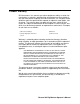
8.50 7.00 4.83 8.0 Max Mounting Feet, 4X Ø .31 x .50 slot, 4X .41 AL AR M 2 FAIL AL AR M 1 PILOT 6.45 10.50 10.94 BEACON 200 GAS MONITOR RESET Buzzer 3/4 Conduit Hubs (4X) Reset Switch 3/4 Cable Bushings (3X) 6.00 Figure 7. Rig Monitor Outline and Mounting Dimensions 1. Select the mounting site.
2. Close and latch the housing door. 3. Position the monitor on a vertical surface at eye level (4 1/2 to 5 feet from the floor). 4. The Rig Monitor is shipped with the mounting feet positioned behind the housing. Loosen the screws that secure the feet to the housing, rotate the feet to their mounting position (as shown in Figure 7), then tighten the screws. 5. Insert 1/4 in. or 5/16 in.
Wiring the Beacon 200 Rig Monitor The detector leads, junction box connections, power cable wiring, and strobe/horn wiring are all factory wired.
WARNING: Make all connections to the Beacon 200 Rig Monitor before you connect the DC power source. Before you make any wiring adjustments, always verify that all power sources are not live. Connecting the DC Power Source Perform the following functions to connect the Rig Monitor to DC power. One end of the battery cable is already factory wired to the appropriate terminals at the Rig Monitor housing. Use the other end to connect a 12 VDC battery.
4. Guide the wiring of the external alarm device through the new conduit hub on the bottom of the Rig Monitor housing. 5. Connect the leads from the external alarm device and power to the alarm terminals as shown in Figure 10. CH 1-A1 NO NC C Beacon 200 Alarm Terminal Strip (+) H (-) N External Power Source External Alarm Device Figure 10. Typical External Alarm Wiring 6. Repeat steps 4 and 5 for additional external alarm devices.
5. Connect the wires form the recording device to the recorder output terminals as shown in Figure 11. Recording Device #1, 1Kohm Max Impedance Recording Device #2, 1Kohm Max Impedance + + CH1 OUT + CH2 OUT + Figure 11. Recorder Output Wiring Starting Up the Beacon 200 Rig Monitor Perform the following procedure to place the Beacon 200 Rig Monitor into normal operation. 1. Complete the mounting and wiring procedures described earlier in this chapter. 2.
Chapter 4: Operation Overview This chapter describes the Beacon 200 Rig Monitor in normal operation. This chapter also describes the Rig Monitor in alarm 1, alarm 2, and fail conditions and suggests response to these conditions. Normal Operation Normal operation is defined as follows: • The start-up procedure is complete. • The Rig Monitor is not indicating an alarm 1, alarm 2, or fail condition. • The Rig Monitor is not running the Channel Control & Setup or Calibration Programs.
Recorder Output Operation The output at the recorder output terminals is a 4 - 20 mA signal for each active channel that is proportional to the detection range of the channel. A channel that is set as CHANNEL NOT USED or CHANNEL DISABLED in the Channel Control & Setup Program (see “Chapter 5: Channel Control and Setup Program” on page 28) has an output of 0 mA.
Alarm Indications This section describes the Rig Monitor in alarm 1, alarm 2, and fail conditions and suggests response to these conditions. Table 5 below lists the alarm indications for each condition. NOTE: The Beacon 200 Rig Monitor includes alarm on and alarm off delay settings for each channel and level of gas alarm. The alarm indications described in this section operate according to the factory set delay settings. See “Configure Channel Settings Menu” on page 30 for all the factory settings.
NOTE: You can select normally energized (NE) or normally de-energized (NDE) channel relay settings in the Channel Control & Setup menu. The following sections describe the default setting for the channel relays which is NDE. Common alarm 1 and alarm 2 relays are factory-set as NDE, and the common fail relay is factory set as NE. The common relays’ NE/NDE settings are not user-adjustable.
Alarm 2 Condition This section describes the audible and visual indications for an alarm 2 condition and suggests response to an alarm 2 condition. Alarm 2 Condition Indications When the gas reading of an active channel reaches the alarm 2 setpoint, the Rig Monitor senses an alarm 2 condition. The Rig Monitor alerts you to an alarm 2 condition as follows: • The ALARM 2 light turns on. • The gas reading in alarm 2 condition continues to flash and alternates with the ALARM-2 messages.
• The display reading is -10% of full scale or lower. • The Rig Monitor or detector head is malfunctioning. When the Rig Monitor senses a fail condition, it alerts you as follows: • The FAIL light turns on. • The gas reading for the failing channel is replaced by the FAIL message. • The buzzer sounds a steady tone. • The common fail relay de-energizes.
Viewing & Resetting Min/Max Readings The Reset switch may be used to view and reset the minimum and maximum gas readings for the active channel(s). 1. While the Rig Monitor is in normal operation, press and hold the Reset switch button for 3 seconds. 2. The display will indicate MIN / MAX Display Press RESET when done viewing . . . for 5 seconds before displaying the minimum and maximum readings for the active channel(s).
Chapter 5: Channel Control and Setup Program Overview The Channel Control & Setup Program allows viewing of and changes to instrument setup parameters. It is accessed using the program buttons. The Channel Control & Setup Program includes three menus as described in Table 6.
Enable/Disable Channel(s) Menu 1. From normal operation, simultaneously press and hold the ESCAPE and ENTER buttons for approximately 5 seconds to enter the Channel Control & Setup Program. Release the buttons when the Control & Setup Program Proceed? [YES] or [NO] message appears on the display screen. 2. Press the UP/YES button to continue. 3. Press the UP/YES or DOWN/NO button until the 1) Enable/Disable Channel(s) message appears on the display screen, then press the ENTER button. 4.
Configure Channel Settings Menu This section describes how to view and change channel parameters for the installed gas channels. 1. Simultaneously press and hold the ESCAPE and ENTER buttons for approximately 5 seconds to enter the Channel Control & Setup Program. Release the buttons when the Control & Setup Program Proceed? [YES] or [NO] message appears on the display screen. 2. Press the UP/YES button to continue. 3.
10.Press the UP/YES button to save the configuration. The screen will then return to the Channel Control & Setup menu. 11.To view or change the Channel 2 settings, scroll to the Configure Channels Menu and repeat steps 4 through 10. 12.To exit the Channel Control & Setup menu, press ESCAPE to return to the screen which asks Control & Setup Program Proceed? [YES] or [NO]. 13.Press the DOWN/NO button to return to normal operation.
Table 8: Channel Setting Parameters (Continued) Parameter (Factory-Set Value) Description ALARM-2 OFF DELAY (0 sec) The amount of time the Rig Monitor delays turning off the alarm 2 circuit once an alarm 2 condition passes. ALARM-2 (activation) (INCREASING) Indicates if the alarm 2 circuit is activated by gas readings INCREASING or DECREASING to the ALARM-2 Level.
Chapter 6: Maintenance Overview This chapter describes use of the Calibration Program and corrective maintenance procedures for the Beacon 200 Rig Monitor. It includes a troubleshooting guide for problems you may encounter with the Beacon 200 Rig Monitor. Procedures to replace components of the Rig Monitor are at the end of this chapter. Calibration Program The Calibration Program is used to calibrate the Rig Monitor’s active channel(s).
ESCAPE Normal Operation Calibration Program Enter ENTER/ESCAPE ENTER Calibration Timeout Selection Calibrate Channel 1 Y/N? Calibrate Channel 2 Y/N? Air Adjust Channel 1 Air Adjust Channel 2 Span Channel 1 Y/N? Span Channel 2 Y/N? Select Cal. Gas Concentration for Channel 1 Select Cal. Gas Concentration for Channel 2 Apply Gas to Ch. 1 & Ch. 2 Detectors Press Enter to Adjust Span Figure 12.
NOTE: While in the Calibration Program, the alarm status of the Beacon 200 Rig Monitor will be locked in the state it was when the Calibration Program was entered. 2. Press the ENTER button to continue and display the Calibration Timeout setting. The Rig Monitor will remain in the Calibration Program for the amount of time indicated by the Calibration Time-out setting or until you exit the program. If necessary, adjust the setting using the UP/YES and DOWN/ NO buttons.
4. Screw the fixed flow regulator into the zero air calibration cylinder. 5. Use the calibration kit sample tubing to connect the fixed flow regulator to the calibration cup/splash guard of the LEL detector. 6. Turn the regulator knob counterclockwise to open the regulator. 7. Allow zero air to flow for two minutes. 8. Turn the regulator knob clockwise to close the regulator. The Rig Monitor will continue to display the minimum gas response on the display and retain the response level in its memory. 9.
If you press the DOWN/NO button, the span of channel 1 will continue if you selected it or if you did not select channel 1, the unit will return to the first calibration program screen which asks if you want to continue or escape from the Calibration Program. 3. If you pressed the UP/YES button for either channel, the display will prompt you for the span gas concentration that will be used for the first selected channel. The following instructions assume you pressed UP/ YES button for each channel. 4.
NOTE: Be sure that you are using an appropriate calibration cylinder for the channel you are calibrating. 14.Connect the sample tubing to the calibration cup/splash guard hose barb of the H2S detector. 15.Turn the regulator knob counterclockwise to open the regulator. 16.Allow the calibration gas to flow for two minutes. 17.Turn the regulator knob clockwise to close the regulator. The Rig Monitor will continue to display the maximum gas response on the display and retain the response level in its memory.
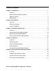
Adjusting Strobe/Horn Volume The horn volume on the strobe/horn can be adjusted by doing the following: 1. Open the housing door of the Rig Monitor, then place the power switch in the OFF position. 2. Disconnect the battery clamps from the + and - terminals of the 12 VDC battery. 3. Loosen the captive screw at the bottom front of the strobe/horn. 4. Grasp the top and bottom of the strobe/horn and push up and out in order to remove the cover. Base Top Captive Screw Push Out Push Up Here Figure 13.
5. Turn the cover over and locate the Audio Select switch at the top of the cover as shown in the figure below. Audio Select Switch 4 5 6 3 2 1 AUDIO SELECT CANDELLA S ELECT Strobe Brightness Switch (DO NOT ADJUST) Figure 14. Strobe/Horn Cover 6. The Audio Select switch can be set at any number between 1 and 6. Numbers 1-3 all produce an intermittent buzzing sound with 1 being the loudest and 3 being the quietest.
Replacing Components of the Rig Monitor This section describes how to replace the fuses, the LEL detector, the plugin H2S sensor, and the entire H2S detector. Replacing the Fuses 1. Open the housing door of the Rig Monitor, then place the power switch in the OFF position. 2. Disconnect the battery clamps from the + and - terminals of the 12 VDC battery. 3. Locate the vertical fuse holders on either side of the power switch. The DC fuses are labelled F2 and F3 and are on the right of the power switch. 4.
4. Disconnect the detector leads from the terminal block in the junction box. Note the position of the color-coded leads as you remove them. 5. Unscrew the calibration cup from the detector. 6. Unscrew the detector from the junction box hub. 7. Guide the detector leads of the replacement detector through the junction box hub then screw the mounting threads of the detector into the hub. 8. Connect the detector leads to the terminal block the same way the old detector was wired.
cap back onto the housing body. 10.Screw the calibration cup/splash guard back onto the detector housing cap. 11.Connect the battery clamps to the + and - terminals of the 12 VDC battery. 12.Place the Rig Monitor’s power switch in the ON position, then verify that the PILOT light is on. CAUTION: Allow the replacement sensor to warm up for 15 minutes before you continue with the next step. 13.Calibrate the detector as described in “Calibration Program” on page 33.
12.Place the Rig Monitor’s power switch in the ON position, then verify that the PILOT light is on. CAUTION: Allow the replacement detector to warm up for 5 minutes before you continue with the next step. 13.Calibrate the replacement detector as described in the Calibration section of this manual. Preventive Maintenance This section describes a preventive maintenance schedule to ensure the optimum performance of the LEL and H2S detectors. It includes daily, monthly, and quarterly procedures.
NOTE: Ensure that you are using an appropriate calibration cylinder for the channel you are testing. 5. Use the calibration kit sample tubing to connect the regulator to the calibration cup/splash guard of the LEL detector. Performing the response test 1. Turn the regulator’s on/off knob counterclockwise to open the regulator. Gas will begin to flow. 2. Allow the gas to flow for one minute, then verify that the reading is within ± 20% of the cylinder gas concentration.
Quarterly Calibrate the LEL and H2S detectors as described in the Calibration section of this manual. Troubleshooting The troubleshooting guide describes symptoms, probable causes, and recommended action for problems you may encounter with the Rig Monitor. Table 9: Troubleshooting the Beacon 200 Rig Monitor Condition No Power Symptom(s) • • The PILOT light is off. The display screens are blank.
Table 9: Troubleshooting the Beacon 200 Rig Monitor (Continued) Condition Buzzer Not Working Symptom(s) • • Reset Switch Not Working • • Strobe/Horn Not Working Fail Condition • • • Probable Causes The buzzer does not sound an audible alarm during alarm conditions. The buzzer sounds weak or broken. • The buzzer does not silence when you press the reset switch. The applicable alarm circuit does not reset when you press the reset switch after an alarm condition passes.
Parts List Table 10 lists the part numbers and descriptions for replacement parts and accessories offered for the Beacon 200 Rig Monitor. Table 10: Parts List, Beacon 200 Rig Monitor Part No. Description 06-1248RK-03 Sample tubing for calibration, 3 foot length 07-0033RK Detector housing cap gasket for H2S detector 07-0203RK Rubber retaining boot for H2S sensor 14-2101RK Spacer between H2S sensor and rubber boot 18-0061RK Cable bushing 18-0107RK Conduit Hub (3/4 in.
Table 10: Parts List, Beacon 200 Rig Monitor Part No.