
Instruction Manual


13 Beacon 110 Rig Monitor Operator’s Manual
Wiring the Beacon 110 Rig Monitor
This section describes procedures to connect external alarm(s) and a recorder to the Rig Monitor.
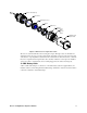
The power, detector, and strobe/horn wiring are all factory wired as shown below.
Figure 7: Rig Monitor Factory Wiring
Strobe / Horn
Beacon 110
Main PCB
24V
L
N
G
Red
Terminal Block
FACTORY
WIRED
ALARM
RESET
ALARM
RESET
ALARM
B U ZZE R
4-2 0mA
OUTP UT
ALARM 1
FAI L
TO 12
VDC
Battery
Terminals
BlackWhite
Battery
Cable
Black
White
Reset
Switch
Black
Power
Converter
OUT
IN
TB1
Conduit Hubs
H2S Detector
GND
Buzzer
Detector
Cable
Black
Red
ALARM 2
PCB
Ground
Red
Black