
Instruction Manual


9 Beacon 110 Rig Monitor Operator’s Manual
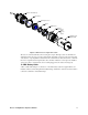
Figure 4: Control PCB Component Location
LCD Display
The LCD display is located at the top of the control PCB. It indicates the current gas reading and
displays messages and parameters in the Rig Monitor’s operating modes.
Contrast Potentiometer
The contrast potentiometer is located to the right of the LCD display. It is used to adjust the contrast
of the LCD. If the background of the LCD appears so dark that the characters are not visible or if
the characters are too dim, turn the adjustment screw on the potentiometer clockwise or
counterclockwise until the desired visibility is obtained.
Control Buttons
The Rig Monitor includes three push button switches that allow you to enter the Rig Monitor’s
operating modes, navigate through the modes, update settings, and save changes to the settings.
The push button switches are located along the bottom edge of the control PCB (see Figure 4). The
UP/YES button is on the left, the DOWN/NO button is in the middle, and the ENTER button is on
the right.
Table 4: Beacon 110 Rig Monitor Control Button Functions
Switch Function
UP/YES • Saves settings
• Changes the displayed setting
• Enters Calibration Mode
• Enters Configuration Mode (press with ENTER button)
DOWN/NO • Cancels setting changes
• Changes the displayed setting
• Displays the Information Screen
UP/YES DOWN/NO
ENTER
F
A1 A2
Control Switches
F
ail LED
Alarm 1 LED
Alarm 2 LED
LCD Display
Contrast
Potentiomet
er