Beacon 110 Rig Monitor Operator’s Manual Part Number: 71-0232RK Revision: C Released: 9/30/14 RKI Instruments, Inc. www.rkiinstruments.
WARNING Read and understand this instruction manual before operating instrument. Improper use of the rig monitor could result in bodily harm or death. Periodic calibration and maintenance of the rig monitor is essential for proper operation and correct readings. Please calibrate and maintain this rig monitor regularly! Frequency of calibration depends upon the type of use you have and the sensor types.
Product Warranty RKI Instruments, Inc. warrants gas alarm equipment sold by us to be free from defects in materials, workmanship, and performance for a period of one year from date of shipment from RKI Instruments, Inc. Any parts found defective within that period will be repaired or replaced, at our option, free of charge.
Table of Contents Chapter 1: Introduction . . . . . . . . . . . . . . . . . . . . . . . . . . . . . . . . . . . . . . . . . . . . . . . . . . . . . . . 1 Overview . . . . . . . . . . . . . . . . . . . . . . . . . . . . . . . . . . . . . . . . . . . . . . . . . . . . . . . . . . . . . . 1 About the Beacon 110 Rig Monitor . . . . . . . . . . . . . . . . . . . . . . . . . . . . . . . . . . . . . . . . . . 1 About this Manual . . . . . . . . . . . . . . . . . . . . . . . . . . . . . . . . . . . . . . . . . . .
Chapter 6: Maintenance . . . . . . . . . . . . . . . . . . . . . . . . . . . . . . . . . . . . . . . . . . . . . . . . . . . . . . 25 Overview. . . . . . . . . . . . . . . . . . . . . . . . . . . . . . . . . . . . . . . . . . . . . . . . . . . . . . . . . . . . . . 25 Calibration Frequency. . . . . . . . . . . . . . . . . . . . . . . . . . . . . . . . . . . . . . . . . . . . . . . . . . . . 25 Calibration Mode . . . . . . . . . . . . . . . . . . . . . . . . . . . . . . . . . . . . . . . . . . . . . . . . .
Chapter 1: Introduction Overview This chapter briefly describes the Beacon 110 Rig Monitor. This chapter also describes the Beacon 110 Rig Monitor Operator’s Manual (this document). Table 1 at the end of this chapter lists the specifications for the Rig Monitor. About the Beacon 110 Rig Monitor The Beacon 110 Rig Monitor is a fixed mount, hydrogen sulfide monitoring controller designed for use at oil drilling sites. All user adjustable parameters may be accessed using push button switches.
Specifications Table 1 lists specifications for the Beacon 110 Rig Monitor. Table 1: Beacon 110 Rig Monitor Specifications Input Power 10.8 - 14.5 VDC, 1A VDC Construction (housing) Fiberglass/polyester with lexan window (NEMA 4X) Dimensions 19 in. H x 7.2 in. W x 5.6 in. D (483 mm H x 183 mm W x 142 mm D) Weight 13 lbs.
Chapter 2: Description Overview This chapter describes external and internal components of the Beacon 110 Rig Monitor.
External Description This section describes the housing and all external components of the Beacon 110 Rig Monitor. For the purposes of this description, the housing door is considered the front of the monitor. Housing The Rig Monitor’s fiberglass housing is weather- and corrosion-resistant. It is suitable for installation where general purpose equipment is in use. The housing door is hinged on the left side and is secured by two latches on the right side.
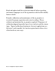
H2S Detector and Cable The H2S detector consists of a junction box with a mounting bracket, the detector, and the calibration cup/splash guard. Mounting B racket To Beacon 110 Cable Bushing Terminal Strip H2S Detector (Factory W ired) Calibration Cup/ Splash Guard Figure 2: H2S Detector Component Location The H2S detector is factory wired through the right cable bushing of the Beacon 110 controller and has a 25 foot cable for remote installation.
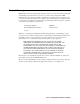
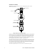
Detector Housing Body Cap Gasket H2S Plug-in Sensor Spacer Rubber Boot Detector Housing Cap Flame Arrestor Guard Calibration Cup/ Splash Guard Figure 3: H2S Detector Component Location The sensor is secured within the sensor housing by four pins. Through a series of chemical and electrical reactions, the sensor produces an electrical output that corresponds to the detection range of the detector.
Internal Description This section describes the internal components of the Beacon 110 Rig Monitor Power Converter The power converter is located underneath the control PCB. It takes 12 VDC voltage supplied to the Rig Monitor and converts it to 24 VDC which is used to run the Rig Monitor. Main Printed Circuit Board (PCB) The main PCB is mounted inside the housing. The main PCB includes the terminal strips, relays, fuses, and power switch.
• Detector/Transmitter Terminal Strips. Three adjacent terminal strips are located along the right side of the main circuit board above the controller terminal strip (see Figure ). These three terminal strips labelled LEL, Oxy, and AMP facilitate wiring connections to a detector or a 4 20 mA transmitter. The Beacon 110 Rig Monitor only uses the top terminal strip, labelled AMP, for wiring to the H2S detector. The LEL and Oxy terminal strips are not used.
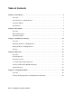
Alarm 1 LED F Fail LED A1 A2 Alarm 2 LED LCD Display Contrast Potentiometer UP/YES DOWN/NO ENTER Control Switches Figure 4: Control PCB Component Location LCD Display The LCD display is located at the top of the control PCB. It indicates the current gas reading and displays messages and parameters in the Rig Monitor’s operating modes. Contrast Potentiometer The contrast potentiometer is located to the right of the LCD display. It is used to adjust the contrast of the LCD.
Table 4: Beacon 110 Rig Monitor Control Button Functions Switch Function ENTER • • • Initiates operations Enters Configuration Mode (press with UP/YES button) Accepts displayed parameters Status LEDs The Rig Monitor includes three active status LEDs that are located above the display (see Figure ). Two LEDs, labelled RX and TX, to the right of those described below, are not active. • Fail LED The fail LED turns on when the Rig Monitor is experiencing a fail condition.
Chapter 3: Installation & Startup Overview This chapter describes procedures to mount the Beacon 110 Rig Monitor, make wiring connections to the monitor, and start up the monitor. WARNING: Perform all installation and start-up procedures in a “fresh air” environment (environment known to be free of toxic gas, and of normal oxygen content). The Beacon 110 Rig Monitor is not in operation as a gas monitoring system until the start-up procedure is complete.
1. Select the mounting site. When you select the mounting site consider the following factors: • Is a DC power source available? • Is there enough room to open the housing door and make wiring connections through the cable bushings at the bottom of the housing? • Are the display screen and status lights on the Rig Monitor visible? 2. If necessary, close and latch the Rig Monitor housing door. 3. Position the monitor on a vertical surface at eye level (4 1/2 to 5 feet from the floor). 4.
Wiring the Beacon 110 Rig Monitor This section describes procedures to connect external alarm(s) and a recorder to the Rig Monitor. The power, detector, and strobe/horn wiring are all factory wired as shown below.
WARNING: Make all connections to the Beacon 110 Rig Monitor before you plug in or turn on the DC power source. Before you make any wiring adjustments, always verify that all power sources are not live. Connecting DC Power Perform the following functions to connect the Rig Monitor to DC power. One end of the battery cable is already factory wired to the appropriate terminals at the Rig Monitor housing. Use the other end to connect a 12 VDC battery.
Connecting Recorders Perform the following procedure to connect an analog signal recording device to the Rig Monitor. The output at the recorder output terminals is a 4 - 20 mA signal that is proportional to the detection range of the H2S detector head connected to the Rig Monitor’s Fail or Alarm 2 terminals. The Alarm 1 terminals are factory wired and not available for field use. 1. Disconnect the battery clamps from the + and - terminals of the 12 VDC battery. 2.
Start Up Introducing Incoming Power Perform the following procedure to place the Rig Monitor into normal operation. 1. Complete the mounting and wiring procedures described earlier in this chapter. 2. Verify that all wiring connections are correct and secure and that the Rig Monitor’s power switch is in the OFF position. 3. If not already connected, connect the battery clamps to the + and - terminals of the 12 VDC battery. 4. Turn on the power switch. 5.
Chapter 4: Operation Overview This chapter describes the Beacon 110 Rig Monitor in normal operation. This chapter also describes the Rig Monitor in alarm 1, alarm 2, and fail conditions and suggests response to these conditions. Normal Operation Normal operation is defined as follows: • The start-up procedure is complete. • The Rig Monitor is not indicating an alarm 1, alarm 2, or fail condition. • The Rig Monitor is not in Calibration or Configuration Mode.
4 - 20 mA Signal Output Operation The output at the 4 - 20 mA output terminals is a 4 - 20 mA signal that is proportional to the detection range of the Rig Monitor. During normal operation, this signal tracks the gas concentration on the LCD. There are several circumstances where the signal output will not track the display reading but will behave as follows: • When the Rig Monitor is in its warm-up period, the signal output will be fixed at 4 mA (zero).
Alarm Indications NOTE: The Beacon 110 Rig Monitor includes alarm on and alarm off delay settings for alarm 1 and alarm 2. The alarm indications described in this section operate according to the factory set alarm settings. See Table 6 on page 23 for all the factory settings.
Alarm 1 Condition Alarm 1 Condition Indications When the gas reading reaches the alarm 1 setpoint, the Rig Monitor senses an alarm 1 condition. The Rig Monitor alerts you to an alarm 1 condition as follows: • The alarm 1 LED turns on. • The gas reading alternates with the ALARM-1 message. • The buzzer sounds a pulsing tone. • The alarm 1 relay energizes and the strobe/horn activates. Responding to an Alarm 1 Condition 1. Follow your established procedure for a toxic gas condition. 2.
Responding to an Alarm 2 Condition 1. Follow your established procedure for a toxic gas condition. 2. The alarms are factory set as latching. After the gas reading falls below the alarm 2 setpoint, press the reset switch to reset the alarm circuit. Resetting the alarm circuit silences the buzzer, turns off the Alarm 2 LED, returns the LCD to the normal operation screen, and de-energizes the alarm 2 relay.
Chapter 5: Configuration Mode Overview This chapter describes how to view and change Beacon 110 Rig Monitor parameters using Configuration Mode. It is accessed using the program buttons. Configuration Mode includes a 5-minute time-out feature. If you do not press a control button for 5 minutes, the Rig Monitor automatically returns to normal operation.
Table 6: Configuration Parameters Parameter (Factory Set Value) Description ALARM-1 (10 ppm) The gas reading at which the Rig Monitor initiates an alarm 1 condition. ALARM-1 (activation) (Increase) Indicates if the alarm 1 circuit is activated by gas readings increasing (Increase) or decreasing (Decrease) to the ALARM-1 Level. • Note: Changing this parameter will affect the operation of the factory installed strobe/horn. Do not change this parameter from the factory setting. ALARM-1 (relay action) (N.
Table 6: Configuration Parameters (Continued) Parameter (Factory Set Value) Description ZeroSupp (2 ppm) The zero suppression feature helps prevent “jumpy” readings near the fresh air reading. For example, if the zero suppression setting for the H2S detector is 2 ppm, the Rig Monitor will display a reading of 0 ppm for gas readings from -2 ppm to 2 ppm. FILTER (5 secs) The filter feature helps “smooth out” jumpy or noisy signals from the detector.
Chapter 6: Maintenance Overview This chapter describes how to calibrate the Beacon 110 Rig Monitor using Calibration Mode, replace the DC fuses, and preventive maintenance procedures for the Rig Monitor. It includes a troubleshooting guide for problems you may encounter with the Rig Monitor. Calibration Frequency Although there is no particular calibration frequency that is correct for all applications, a calibration frequency of every 3 to 6 months is adequate for most Rig Monitor applications.
Calibration Program Flow Figure 10 below illustrates the general flow of the Calibration Program for a direct connect detector. See the next section, “Preparing for Calibration”, for instructions to enter Calibration Mode. In general, if a question mark, “?”, is part of the display text, use the UP/YES or DOWN/NO button to respond.
1. While in normal operation, press and hold the UP/YES button for 5 seconds to enter Calibration Mode. Release the button when the following screen appears. Calib? YES/NO 2. If you want to exit Calibration Mode, press and release the DOWN/NO button. The Rig Monitor will indicate Leaving CAL Mode and the Rig Monitor will return to normal operation. If you want to continue with calibration, press and release the UP/YES button.
Setting the Response Reading 1. Screw the regulator into the calibration gas cylinder. 2. If you want to skip adjusting the span setting, press and release the DOWN/NO button. The display will indicate Leaving Cal Mode and the Beacon 110 Rig Monitor will return to normal operation. If you want to continue with adjusting the span setting, press and release the UP/YES button. APPLY will alternate with SPAN Gas on the top display line and the current gas reading will be on the bottom display line. 3.
Adjusting Strobe/Horn Volume The horn volume on the strobe/horn can be adjusted by doing the following: 1. Open the housing door of the Rig Monitor, then place the power switch in the OFF position. 2. Disconnect the battery clamps from the + and - terminals of the 12 VDC battery. 3. Loosen the captive screw at the bottom front of the strobe/horn. 4. Grasp the top and bottom of the strobe/horn and push up and out in order to remove the cover.
7. Turn the Audio Select switch so that the selection arrow is pointing to the desired number. 8. Place the cover over the base and push in and down in order to reinstall the cover. Make sure that the cover is sealed to the base by the gasket. 9. Screw the captive screw at the bottom front of the strobe/horn back in. Replacing Components of the Rig Monitor This section describes how to replace the fuses, the H2S sensor, and the entire detector assembly.
cap gasket. 5. Unplug and remove the H2S sensor with the rubber boot and spacer attached. 6. Remove the rubber boot and spacer from the old sensor. 7. Install the spacer and rubber boot onto the replacement sensor’s face. 8. Carefully plug the replacement sensor into the four-socket pattern that is located in the detector housing. 9. Make sure the cap gasket is in place and screw the detector housing cap back onto the detector housing body. 10.
Preventive Maintenance This section describes a preventive maintenance schedule to ensure the optimum performance of the H2S detector. It includes daily, monthly, and quarterly procedures. Daily Verify a display reading of 0 PPM H2S at the controller. Investigate significant changes in the display reading. Monthly This procedure describes a test to verify that the H2S detector responds properly to hydrogen sulfide. It describes a test using a fixed flow regulator with an on/off knob. RKI Instruments, Inc.
Troubleshooting The troubleshooting guide describes symptoms, probable causes, and recommended action for problems you may encounter with the Beacon 110 Rig Monitor. Table 7: Troubleshooting the Beacon 110 Rig Monitor Condition No Power Symptom(s) • The display backlight is off and the display screen is blank.
Table 7: Troubleshooting the Beacon 110 Rig Monitor (Continued) Condition Buzzer Not Working Symptom(s) • • Reset Switch Not Working • • Strobe/Horn Not Working Fail Condition • Probable Causes The buzzer does not sound an audible alarm during alarm conditions. The buzzer sounds weak or broken. • The buzzer does not silence when you press the reset switch. The alarm 1 or alarm 2 circuit does not reset when you press the reset switch after the alarm condition passes.
Table 7: Troubleshooting the Beacon 110 Rig Monitor (Continued) Condition Slow or No Response/ Difficult or Unable to Calibrate Symptom(s) Probable Causes Recommended Action • Detector responds slowly or does not respond during response test. • Unable to accurately set the zero or response reading during calibration. • Detector requires frequent calibration. • The calibration cylinder is low, out-dated, or defective.
Parts List Table 8 lists replacement parts and accessories for the Beacon 110 Rig Monitor.
Appendix A: Control Button Quick Reference Guide The Beacon 110 Rig Monitor’s control buttons and reset switch allow access to operational modes, resetting of alarms, and display of the Information Screen. Table 9 shows which button combinations perform these functions and which parameters are available for adjustment while in the operational modes. While in these modes, display prompts showing a “?” require you to respond by pressing either the UP/YES (for yes) or DOWN/NO (for no) button.