
User Manual

Beacon 100 Gas Monitor Operator’s Manual Internal Description • 7
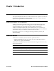
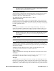
Internal Description
This section describes the internal components of the Beacon 100.
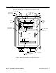
Figure 1: Beacon 100 Gas Monitor Component Location
PILOT Light
ALARM 3 Light
ALARM 2 Light
ALARM 1 Light
FAIL Light
AC/DC Power
Terminal Strip
Reset Switch/
Buzzer
3/4" Conduit
Hub (2)
Right Hand Terminal
Strip (Buzzer, Reset,
24 VDC Out)
Main PC Board
Display PC
Board
DC Fuse,
1.5Amp
(on Main PC
Board)
AC Fuse,
500mA
(on Main PC
Board)
External Alarm, Detector, and
Analog Output Terminal
Strips
ENTERDOWN
FAIL
DISPLAY
UPESCAPE
ALARM 3
ALARM 2
ALARM 1
PILOT
Control
Buttons (4)
ALARM3
Relay
ALARM2
Relay
ALARM1
Relay
FAIL
Relay