Beacon 100 Gas Monitor Operator’s Manual Part Number: 71-0035RK Revision: A Released: 12/2/02 RKI Instruments, Inc. • 1855 Whipple Rd.
Warranty RKI Instruments, Inc., warrants gas alarm equipment manufactured by RKI and sold by RKI to be free from defects in materials and workmanship for a period of one year from date of shipment from RKI Instruments, Inc. Any parts found defective within that period will be repaired or replaced, at our option, free of charge. This warranty does not apply to items that are subject to deterioration or consumption in normal service, and which must be cleaned, repaired, or replaced routinely.
Table of Contents Chapter 1: Introduction . . . . . . . . . . . . . . . . . . . . . . . . . . . . . . . . . . . . . . . . . . . . . . . . . . . . . . . 4 Overview . . . . . . . . . . . . . . . . . . . . . . . . . . . . . . . . . . . . . . . . . . . . . . . . . . . . . . . . . . . . . . . . . . . . . . . . . . . . 4 About the Beacon 100 Gas Monitor . . . . . . . . . . . . . . . . . . . . . . . . . . . . . . . . . . . . . . . . . . . . . . . . . . . . . . 4 About this Manual . . . . . . . . . . . . . . . . .
Chapter 1: Introduction Overview This chapter briefly describes the Beacon 100 Gas Monitor. This chapter also describes the Beacon 100 Gas Monitor Operator’s Manual (this document). Table 1-1 at the end of this chapter lists the specifications for the Beacon 100. About the Beacon 100 Gas Monitor The Beacon 100 is a fixed-mounted, continuous-monitoring instrument. This single channel gas monitor is capable of detecting gas at one location.
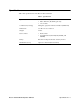
Specifications Table 1 lists specifications for the Beacon 100 Gas Monitor. Table 1: Specifications Input Power • 100 to 125 VAC, 50/60 Hz • 200 to 250 VAC, 50/60 Hz (optional) • 11 to 16 VDC Construction (housing) Fiberglass/polyester with lexan window (NEMA 4X) Dimensions 9 in. H x 7 in. W x 4.5 in. D Weight 4.2 lbs.
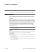
Chapter 2: Description Overview This chapter describes external and internal components of the Beacon 100 Gas Monitor. External Description This section describes the housing and all external components of the Beacon 100. For the purposes of this description, the housing door is considered the front of the monitor. Housing The Beacon 100’s fiberglass housing is weather- and corrosion-resistant. It is suitable for installation where general purpose equipment is in use.
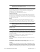
Internal Description This section describes the internal components of the Beacon 100. PILOT Light ALARM 3 Light Main PC Board ALARM 2 Light Display PC Board ALARM 1 Light PILOT AC Fuse, 500 mA (on Main PC Board) FAIL Light FAIL DC Fuse, 1.
Fuses The Beacon 100 includes one AC fuse (0.5 amp) and one DC fuse (1.5 amp). AC fuse The AC fuse holder is underneath the display board on the left hand side near the left edge of the main circuit board. The AC fuse protects the AC line circuitry from short circuit or overload. The AC fuse is rated at 0.5 amps. NOTE: The standard configuration is for 115 VAC operation. 220 VAC operation is an optional configuration and must be specified when ordering.
NOTE: See the detector head operator’s manual and the Beacon 100 Detector Head Specification Sheet for the installed detector head to wire the detector head to the appropriate detector terminal strip connections. Analog Output terminal strip The 2-point analog output terminal strip (labeled 4-20 mA out) is directly to the right of the detector terminal connections. You connect wiring from a recording device (if applicable) to the analog output terminal strip.
respond to a fail condition. ALARM 1 light The ALARM 1 light is to the left of the display screen. The ALARM 1 light turns on when the Beacon 100 is experiencing an Alarm 1 condition (see Chapter 4, Operation). ALARM 2 light The ALARM 2 light is to the left of the display screen and above the ALARM 1 light. The ALARM 2 light is on when the Beacon 100 is experiencing an Alarm 2 condition. ALARM 3 light The ALARM 3 light is to the left of the display screen and above the ALARM 2 light.
Chapter 3: Installation and Start Up Overview This chapter describes procedures to mount the Beacon 100 Gas Monitor, make wiring connections to the monitor, and start up the monitor. WARNING: Perform all installation and start-up procedures in a “fresh air” environment (known to be free of combustible gas, toxic gas, and of normal oxygen content). The Beacon 100 is not in operation as a gas monitoring system until the start-up procedure is complete.
Mounting the Beacon 100 Gas Monitor Perform the following procedure to install the instrument housing at the mounting site. 1. Select the mounting site. When you select the mounting site consider the following factors: • Is an AC or DC power source available? • Is there enough room to open the housing door and make wiring connections through the conduit hubs at the bottom of the housing? • Are the display screen and status lights visible? 2. If necessary, close and latch the housing door. 3.
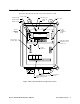
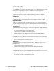
Hot H Neutral N Ground G + + - - A C P o w e rI n 115 VAC,60Hz Optional.) (230VAC 12 VDC Backup Power In 24 VDC Out, 100 mA max + 12 VDC Input - 24 VDC + OUT.
Wiring the Beacon 100 Gas Monitor This section describes procedures to connect the AC power source, DC power source, external alarm(s), recorder, and detector. See Figure 3 for a general wiring diagram of all external wiring to the Beacon 100. WARNING: Make all connections to the Beacon 100 before you plug in or turn on the AC or DC power source. Before you make any wiring adjustments, always verify that all power sources are not live.
Connecting External Alarms Perform the following procedure to connect external alarms to the Beacon 100. 1. Open the housing door, and locate the external alarms terminal strip. See Figure 1, Beacon 100 Gas Monitor Component Location on page 7, to assist you in locating the external alarms terminal strip. 2. Guide the wiring of the external alarm through one of the conduit hubs on the bottom of the Beacon 100 housing.
Starting Up the Beacon 100 Gas Monitor Perform the following procedure to place the Beacon 100 into normal operation. 1. Complete the mounting and wiring procedures described earlier in this chapter. 2. Complete all installation procedures in the detector head or user supplied 4 - 20 mA transmitter. 3. Verify that all wiring connections are correct and secure. 4. Plug in or turn on the incoming power source (AC or DC).
Chapter 4: Operation Overview This chapter describes the Beacon 100 Gas Monitor in normal operation. This chapter also describes the Beacon 100 in alarm 1, alarm 2, alarm 3, and fail conditions and suggests response to these conditions. The Instrument Setup program is described at the end of this chapter. Normal Operation Normal operation is defined as follows: • the start-up procedure is complete. • the Beacon 100 is not indicating an alarm 1, alarm 2, alarm 3, or fail condition.
Table 2: Visual and Audible Alarm Indications Condition Cause Alarm 1 Increasing (decreasing for O2) gas reading at or above the alarm 1 setpoint • ALARM 1 light is on Increasing (decreasing for O2) gas reading at or above the alarm 2 setpoint • ALARM 1 and ALARM 2 lights are on Alarm 2 Visual Indication Increasing gas reading at or above the alarm 3 setpoint Pulsing tone • Gas reading flashes • Gas reading flashes Alarm 3 Audible Indication • ALARM 1, ALARM 2, and ALARM 3 lights are on* Fast
2. After the gas reading falls below the alarm 1 setpoint, press the reset switch to reset the alarm 1 circuit. Resetting the alarm 1 circuit silences the buzzer, turns off the ALARM 1 light, and de-energizes the alarm 1 relay. NOTE: To silence the buzzer while in an alarm 1 condition, press the reset switch. You cannot de-energize the alarm 1 relay until the gas reading falls below (above for oxygen) the alarm 1 setpoint.
Responding to an alarm 3 condition This section suggests response to an alarm 3 condition. 1. Follow your established procedure for a high level combustible or toxic gas condition or an increasing oxygen content condition. 2. After the gas reading falls below the alarm 3 setpoint, press the reset switch to reset the alarm 3 circuit. Resetting the alarm 3 circuit turns off the ALARM 3 light, and de-energizes the alarm 3 relay. NOTE: The alarm 3 condition cannot be silenced.
Instrument Setup Program This section describes the Instrument Setup program. You can display and change the following instrument settings with the Instrument Setup program.
Running the Instrument Setup Program This section describes how to enter the program, display and change program settings, and save or cancel changes to the program settings. Entering the instrument setup program 1. Open the housing door, and locate the program buttons below the display screen. 2. Press the ESCAPE and DOWN buttons simultaneously and hold for 3 seconds. The display screen changes from the gas reading screen to a screen that gives you a choice of CALIB or ALARMS & MISC. 3.
NOTE: If alarm 1 is silenced when the alarm logic is set to latching, the alarm 1 relay will de-energize after the gas reading falls below the alarm 1 setpoint To access the alarm logic setting, move the cursor in front of the current setting, LATCH or AUTO, and press the ENTER button. • • To update the alarm logic setting: 1. Use the UP or DOWN button to display the setting you want (either LATCH for latching alarms, or AUTO for auto reset alarms) 2.
Alarm Adjustments Screen If ENTER is pressed with the cursor in front of ALARM, you can choose an alarm level, ALARM 1, ALARM 2, or ALARM 3, for which the following settings can be changed: alarm levels, relay action (normally energized or de-energized alarms), and alarm type (rising or falling alarms). To access any of the above settings for a particular channel, move the cursor in front of the alarm level desired with the UP and DOWN buttons and press ENTER.
• To update the alarm type setting: 1. Use the UP and DOWN buttons to change the current setting to the desired setting, RISE or FALL. 2. Press ENTER to accept the new setting and it will stop flashing. If you press ESCAPE while the setting is still flashing, any change you may have made will be cancelled and the original setting will be displayed. Returning to Normal Operation Press ESCAPE four times to return to normal operation.
Chapter 5: Maintenance Overview This chapter describes use of the Calibration Program and corrective maintenance procedures for the Beacon 100. It includes a troubleshooting guide for problems you may encounter with the Beacon 100. Procedures to replace components of the Beacon 100 are at the end of this chapter. Calibration Program The Calibration Program is used to calibrate the detector head installed on the Beacon 100.
NOTE: Once you leave normal operation and enter this screen, if any alarm conditions were occurring when you left normal operation, they will be retained by the Beacon 100 until you return to normal operation. If an alarm condition no longer exists when you return to normal operation, press the reset switch to reset alarms. 4. Press the UP or DOWN button to make the cursor blink in front of CALIB, then press the ENTER button to enter the Calibration Program.
3. Press the ENTER button to perform a zero adjust. The screen will momentarily show WAIT and then indicate ZERO COMPLETE. 4. Press ESCAPE to return to the ZERO/SPAN screen 5. Use the DOWN button to make the cursor blink in front of SPAN. Press ENTER 6. The screen will display the concentration of calibration gas that it expects when you perform the span operation.
button to perform a zero adjust. The screen will momentarily show WAIT and then indicate ZERO COMPLETE. 9. Allow enough time for the gas reading to return to normal and then press ESCAPE three times to return to normal operation. NOTE: If you do not allow the gas reading to return to normal, then unwanted alarms may occur. Preventive Maintenance Preventive maintenance of the Beacon 100 consists of daily, monthly, and quarterly procedures to ensure that the detector reading remains on zero (20.
Frequent or Suspect Alarms Symptoms • The Beacon 100 alerts you to frequent or suspect alarms, but the detector’s fresh air readings remain on zero (20.9 for oxygen). Probable causes • The Beacon 100 is experiencing false readings due to Radio Frequency Interference (RFI) or Electromagnetic Interference (EMI). • The detector wiring is disconnected, misconnected, or intermittent. Recommended action 1. Verify that the detector wiring is properly shielded (see the detector operator’s manual). 2.
The Buzzer is not Working Properly Symptoms • The buzzer does not sound an audible alarm when the Beacon 100 goes into an alarm 1, alarm 2, alarm 3, or fail condition. • The buzzer sounds weak or broken. Probable causes • The buzzer is disconnected. • The buzzer is connected incorrectly. • The buzzer is malfunctioning. Recommended action 1. Open the housing door of the Beacon 100, then verify that the buzzer wiring to the right hand terminal strip is correct and secure.
Replacing Components This section describes procedures to replace the fuses. To replace other components of the Beacon 100, contact RKI Instruments, Inc., for further information. Replacing the AC Fuse This section describes the procedure to replace the AC fuse. 1. Unplug all incoming power to the Beacon 100 at the power source end. 2. Open the housing door of the Beacon 100. 3. Remove the four screws which secure the display PCB to the four standoffs that are mounted to the main PCB. 4.
Parts List The table below lists the part numbers and descriptions for replacement parts and accessories offered for the Beacon 100 Gas Monitor. Table 4: Parts List for the Beacon 100 Gas Monitor Part No. Description 18-0107RK Conduit Hub (3/4 in.) 43-0440RK Reset Switch 43-4138RK AC Fuse, 115V (1/2 amp; 250V) 43-4145RK DC Fuse (1.