
User Manual


65-2649RK-HC-04 M2A Tran smitter Op erator’s Manual 4
M2A Junction Box
The M2A’s cast aluminum junction box protects the terminal PCB and wiring connections
made to the terminal PCB. Use the three 3/4 in. conduit hubs to wir e the remotely installed IR
LEL detector and con nect wiring fr om an external d evice, typ ically an RKI controller. The top hub
is shipped with a factory installed and sealed conduit plug to avoid leaks into the junction box. If
necessary, the conduit plug can be removed and the top hub can be used for wiring.
WAR NING: If the top conduit hub is used for wiring, be sure to seal t he thread s to ensure
water does not enter the junction box. See “Wiring the M2A Transmitter” on
page 11 for complete wiring instructions.
Use the juncti on box’s two mounting slots to mount the M2A to a vertical surface at the
monitoring site. The window in the cover on the front of the junction box all ows you to
view the OLED display and use the magnetic wand to actuate the magnetic control
switches so you can perform non-intrusive calibration. Removing the cover allows you to
access the interior of the junction box.
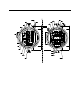
Detector Junction Box
The detector junction box is intended to be installed remotely from the M2A junction box.
The IR LEL detector is factory instal led in th e bottom 3/4” NPT conduit hub. A terminal
strip is provided for wiring connections and the detector is factory wire d to one side of
this terminal strip. The other side of the terminal strip is for user-supplied wiring to the
detector terminal strip located in the M2A junction box. This wiring should go through
the top 3/4” conduit hub. Three spacers installed on the back of the junction box controls
the distance of the junction box from a mounting surface.
Infrared LEL Detector
The infrared LEL detector is made up of a miniature infrared combustible gas LEL
detector housed and encapsulated in a pipe n ipple. The pipe nipple has 3/4” NPT thr eads
on each end and a 1 1/4” hex that allows removal or installation of the detector with a
wren ch. A porous flame arrestor that i s coated w ith a hyd r opho bic film th at r e pels liq uids
is on o ne end of the detector and al lows samp le gas to enter the detector. Four color coded
leads, red, white, green, and black, extend from the other end of the detector. The leads
allow you to connect the detector to the termin al strip.
Calibration Adapter/Splash Guard
A calibration adapter/splash guard is installed on the IR LEL detector. A fitting at the
bottom of the cal ibra tion adapter/spla sh guard allows a length of tubin g to be connected
for calibration and routed to a more easily accessible location (near the M2A junction box
is optimal for ease of calibration). The calibration adapter/splash guard also protects the
detector from splashing water or direct water spray.
Magnetic Wand
The magnetic wand is a short plastic rod with a magnet in one end. It is used to actuate
the magnetic control switches on the control PCB while the junction box cover is still
installed so tha t non-intrusive calibration can be performed.