
User Manual


65-2649RK-HC-04 M2A Tran smitter Op erator’s Manual 48
Appendix B: PLC an d DCS Device Wiring
The M2A can be wired to a PLC or DCS device if desired.
1. Guid e multi conductor sh ield ed cable or cables or wires in conduit through the top
conduit hub of the junction box. The number of cables or wire s needed will depend on
whether any relays are used and whether the Modbus output is used. Use the
following recommendations to determine how to wire the M2A :
• If Modbus connections will not be used and only the PWR/SIG term inal strip
connections will be used, use four conductor shielded cable or four wires in
conduit for connections to the power/signal terminal strip.
• If the PWR/SIG terminal strip connections and one or mor e r elays ar e used, route
the connections to the M2A in conduit. Use shielded cable in the conduit for the
PWR/SIG con nections and unshielded cable or individual wires for the relay
connections. Ma ke sure an y wire or cable used for relay wiring is appropriately
rated for the power that it will carry.
NOTE: If shielded cable is used for the PWR/SIG connections, leave the cable shield’s
drain wire insulated and disconnected at the M 2A. You will connect the
opposite end of the cable’s drain wire at the controller or device.
• If th e M2 A w ill be wired into a Modbus n etw or k, see “Chapter 8: RS-485 Modbus
Output” on page 36.
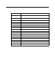
Table 15: Wire Size for PWR/SIG Connections
Max Distance to Controller
w/18 Gauge Wire
Max Distance to Controller
w/16 Ga u ge Wire
Max Distance to Controller
w/14 Gauge Wire
2,500 ft. 5,000 ft. 8,000 ft.