
User Manual


65-2649RK-HC-04 M2A Tran smitter Op erator’s Manual 14
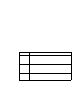
See Figure 7 below for field wiring connections to the M2A.
Figure 7: Wir ing the M2A Junction Box to a Controller and Alarm Devices
16. Re-insta ll the control PCB (and ribbon cable if necessary). Be sure the ribbon cable is
routed down below the control PCB so it will not be damaged by the cover w hen it is
scre wed back on.
17. Secure the M2A junction box cover to the jun ction box.
18. Make controller, device, and relay connections as appropriate. If shielded cable is
used for the PWR/SI G connections, connect the cable shield’s drain w ire to an
available chassis ground at the gas monitoring controller, recording de vice, or
programma b le c on t roller.
Fail
Alarm
Devic e
Alarm 1
Alarm
Devic e
Alarm Device
Power
(24 VDC ) +
Typical Alarm
Wiring Shown
See
Modbus
Wiring
4 - 20 mA In (S)
(24 VDC) -
RKI Controller
Terminals
C NC NO
ALARM 1
C NC NO
ALARM 2
C NC NO
FAIL
Cabl e Shield
- S +
A B C
RS 485 PWR/SIG
R W G B
LEL
See
Detector
Wiring
Alarm 2
Alarm
Devic e