
User Manual


1 3 65-2649RK-HC-04 M2A Transmitter Operator’s Manual
14. If shielded cable is used between the detector junction box and the M2A junction box,
connect the cable’s drain wire to an available chassis (earth) groun d a t the M2A
junction box. Do n ot con nect the shield drain wire at the detector junction box.
15. Guide multi conductor sh ield ed cable or cables or wires in conduit through the side
conduit hub of the M2A junction box. The number of cables or wires needed will
depend on whether the M2A is wired to a gas monitoring controller or just to power,
whether any relays are used, and whether the Modbus output is used.
WARNING: If the top conduit hub is used for wiri ng, be sure to s eal the th reads to
ensure water does not enter the junction box. A condui t seal, which is
normally required to maintain the jun c tion box’s hazardous location
rating, will also help to prevent water from entering through the top port.
NOTE: If the M2A is being wired to a PLC or DCS device, see “Appendix B: PLC and
DCS Device Wiring” on page 48, then continue with step 8.
Use the following recommendations to determi ne ho w to wire the M2A:
• If Modbus connections will not be used and only the PWR/SIG connections will
be used, use a two or three conductor shielded cable or two or three wires in
conduit for connections to the power/signal terminal strip depending on whether
or not the signal (S) terminal is used. The S terminal has a 4 - 20 mA output, but if
you do not need to m onitor this sign al and do not connect to the S terminal to
access this signal, the M2A will still function completely.
• If the PWR/SIG connections and one or more relays are used, route the
connections to the M2A in conduit. Use shielded cable in the conduit for the
PWR/SIG con nections and unshielded cable or individual wires for the relay
connections. Ma ke sure an y wire or cable used for relay wiring is appropriately
rated for the power that it will carry.
CAUTION: If shielded cable is used for the PWR/SIG connections, leave the cable shield’ s drain
wire insulated and disconn ect ed at the M2A junction box. You will conn ect the
opposite end of the cable’s drain wire at the controller or device.
• If th e M2 A w ill be wired into a Modbus n etw or k, see “Chapter 8: RS-485 Modbus
Output” on page 36.
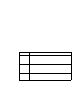
Table 3: Wire Size for PWR/SIG Connections
Max Distance to Controller
w/18 Gauge Wire
Max Distance to Controller
w/16 Ga u ge Wire
Max Distance to Controller
w/14 Gauge Wire
2,500 ft. 5,000 ft. 8,000 ft.