
User Manual


65-2649RK-HC-04 M2A Tran smitter Op erator’s Manual 12
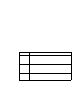
12. Pull out the detector terminal strip and connect the four wires to the terminal strip as
follows (see Figure 6).
• Connect the wire corresponding to the detector’s red wire to the LEL “R”
terminal.
• Connect the wire corresponding to the detector’s white wire to the LEL “W”
terminal.
• Connect the wire corresponding to the detector’s green wire to the LEL “G”
terminal.
• Connect the wire corresponding to the detector’s black wire to the LEL “B”
terminal.
CAUTION: If shielded cable is used, lea ve the cable shield’s drain wire disconnected and
insulated at the detector junction box. You will connect the opposite end of the cable’ s
drain wire to the M2A junction box’s chassis (earth) ground.
Figure 6: Wiring the Detector to the M2A
13. Reinstall the detector terminal strip into its socket.
Red
White
Gr een
Black
Cable
S hield
Detector
Ter m inal
Strip
Green
White
Black
Red
Detector J- Box
M2A
J-Box
IR LE L Detector
Calibration Adapter/Splash G uard
C NC NO
ALARM 1
C NC NO
ALARM 2
C NC NO
FAIL
- S +
A B C
RS 485 PWR/ SIG
R W G B
LEL