
User Manual


65-2649RK-HC-04 M2A Tran smitter Op erator’s Manual 10
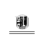
Figure 5: Outline & Mounting Dimensions, Detector Junction Box
3. Install 3/16 inch I.D. flexible polyurethane tubing to the fitting at the bottom of the
calibration adapter/splash guard an d route it to an accessible area that is close to the
M2A junction box. See the “Parts List” on page 46 for available tubing.
IR LEL
Detector
2.70 .38
.75
J-Bo x
Rubbe
r
S pacer
,
3X
3.65
3/4 NPT
Female
Cali bration
A dapt er/
S plash Guar d
9.00 MA X
5.25