
User Manual


65-2649RK-HC-04 M2A Tran smitter Op erator’s Manual 6
Power/Signal Terminal Strip
The power/sign al terminal s trip is a three position plug-in styl e terminal strip located at
the top of the left terminal column. It is used to connect 24 VDC power to the M2A and to
connect the 4 - 20 mA output signal to a device.
The signal output, the S terminal, does not have to be connected for the M2A to function.
The S terminal is used if you want to connect the 4 - 20 mA output signal to another device
such as a gas monitoring controller, chart recorder, or programmable controller (PLC).
Detector Terminal Strip
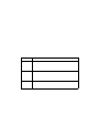
The detector terminal strip is a four position plug-in style terminal strip and is the middle
terminal strip in the left terminal column. All four terminals a re used to connect the
detector to the M2A.
Figur e 3: Det e c tor Terminal Strip
NOTE: The detector is factory-wired to the M2A. See “W iring the M2A T ransmitter” on
page 11 for all wiring procedures related to M2A.
Modbus Terminal Strip
The Modbus terminal strip is a three position plug-in sty le terminal strip and is the
bottom term inal strip in the left terminal column. It a llows connection of the M2A into a
Modbus network .
Relay Terminal Strips
The right column of terminal strips consists of, from top to bottom, the f ail, alarm 1, and
alarm 2 relay t er minal strip s. They are three-p osition plu g -in style terminal strips. The
relay terminal strips are used to connect devices such as lights and horns that are
controlled by the relay contacts. The relay contacts ar e rated at 115 VAC, 5 amps. The relay
contacts may also be used to control higher rated relays.
Termination Jumper
A two pi n header with a termination jumper installed is located below the Modbus
terminal strip. Leave this jumper in stalled unless directed to remove it for a Modbus
Detector
Terminal
Strip
- S +
A B C
RS 485 PWR/SIG
R W G B
LEL
C NC NO
ALAR M 1
C NC NO
ALARM 2
C NC NO
FAIL