
User guide

5 65-2649RK-CH4-4 M2A Transmitter Operator’s Manual
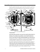
Internal Description
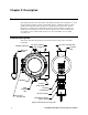
This section describes the internal components of the M2A. The internal components of
the M2A include the terminal PCB which provides for all the wiring connections to the
M2A and the control PCB which displays the gas reading and has the control buttons.
Figure 2: M2A Internal Components
Terminal PCB
The terminal PCB is encapsulated in epoxy for protection against moisture and physical
damage. It is mounted into the rear of the junction box with three standoffs and rests on a
thin layer of foam. A banana jack is screwed into each of the standoffs and used for
mounting the control PCB. The terminal PCB converts the electrical output from the
detector to a signal which can be displayed by the OLED display, a 4 - 20 mA signal (that
is proportional to the detection range), and an RS-485 Modbus output signal. The 4 - 20
mA signal may be used by a recording device, gas monitor controller, or programmable
controller. The Modbus output may be used to connect the M2A to a Modbus network.
The terminal PCB also controls three relays, one fail and two gas alarm relays.
Two columns of plug-in style terminal strips are used to make all wiring connections to
the M2A. The column on the left consists of the power/signal, detector, and Modbus
terminal strips. The column on the right consists of the relay terminal strips. A 20 position
connector at the bottom of the terminal PCB is used to connect the terminal PCB to the
control PCB with a ribbon cable. A 5 position connector on the left side of the terminal
PCB is used by factory or field service personnel to program the M2A. A factory adjust pot
just above the programming connector is used to set the detector current.
TX LED
RX LED
Alarm 2 LED
NO
ENTER
DOWN/NO
3/4" NPT
Conduit
Opening
for Wire
Entry
- S +
A B C
R S 485 PWR/SIG
R W G B
LEL
Magnetic
Switches
Junction Box
Terminal PCB
Fail LED
Alarm 1 LED
Termination Jumper
Modbus Terminal Strip
Programming
Connector
(Factory Use)
Ground Jumper
Detector Terminal Strip
(Comb/CO2 Version Shown)
C NC NO
ALARM 1
C NC NO
ALARM 2
C NC NO
FAIL
UP/YES
DOWN/NO
Push Button
Control
Switches
Control PCB
Detector Current
Adjust Pot
(Comb/CO2 TypeOnly,
Factory Adjust)
ENTER
UP/YES
M2A TRANSMITTER
RKI INSTRUMENTS
OLEDDisplay
View With Cover Removed
View With Cover and
Control PCB Removed
Ribbon Cable Connector
3/4" NPT Conduit Opening, Plugged
Power/Signal
Terminal Strip
Relay
Terminal
Strips