
Manual


65-2619RK-CH4-4 M2 Transmitter Operator’s Manual 10
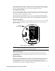
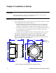
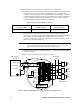
Figure 5: Outline & Mounting Dimensions, Detector Junction Box
3. Install 3/16 inch I.D. flexible polyurethane tubing to the fitting at the bottom of the
calibration adapter/splash guard and route it to an accessible area that is close to the
M2 junction box. See the “Parts List” on page 45 for available tubing.
.382.70
Rubbe
r
Spacer
,
3X
J-Box
.75
3/4 NPT
Female
3.65
IR LEL
Detector
9.00 MAX
Calibration
Adapter/
Splash Guard
5.25