
User guide

65-2615RK-05-04 M2 Transmitter Operator’s Manual 50
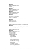
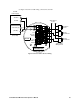
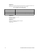
See Figure 12 below for field wiring connections to the M2.
Figure 12: PLC and DCS Device Wiring
Fail Alarm
Device
Alarm 1
Alarm Device
Alarm Device
Power
+
FAIL
C NC NO
PWR/SIG
S
Alarm 2
Alarm Device
Typical Alarm
Wiring Shown
24 VDC
Power Supply
24 VDC +
4 - 20 mA In (S)
(24 VDC) -
ALARM 2
RS 485
A B C
24 VDC -
See
Modbus
Wiring
See
Detector
Wiring
Controller
(PLC, DCS)
TOXIC OXY
+
ALARM 1
C NC NO
C NC NO