
User guide

49 65-2615RK-05-04 M2 Transmitter Operator’s Manual
Appendix B: PLC and DCS Device Wiring
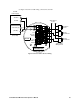
The M2 can be wired to a PLC or DCS device if desired.
1. Guide multi conductor shielded cable or cables or wires in conduit through the top
conduit hub of the junction box. The number of cables or wires needed will depend on
whether any relays are used and whether the Modbus output is used. Use the
following recommendations to determine how to wire the M2:
• If Modbus connections will not be used and only the PWR/SIG terminal strip
connections will be used, use four conductor shielded cable or four wires in
conduit for connections to the power/signal terminal strip.
• If the PWR/SIG terminal strip connections and one or more relays are used, route
the connections to the M2 in conduit. Use shielded cable in the conduit for the
PWR/SIG connections and unshielded cable or individual wires for the relay
connections. Make sure any wire or cable used for relay wiring is appropriately
rated for the power that it will carry.
NOTE: If shielded cable is used for the PWR/SIG connections, leave the cable shield’s
drain wire insulated and disconnected at the M2. You will connect the opposite
end of the cable’s drain wire at the controller or device.
• If the M2 will be wired into a Modbus network, see “Chapter 8: RS-485 Modbus
Output” on page 37.
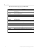
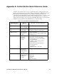
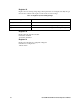
Table 15: Wire Size for PWR/SIG Connections
Max Distance to Controller
w/18 Gauge Wire
Max Distance to Controller
w/16 Gauge Wire
Max Distance to Controller
w/14 Gauge Wire
2,500 ft. 5,000 ft. 8,000 ft.