65-2615RK-05-04 M2 Transmitter Operator’s Manual Part Number: 71-0326 Revision: P1 Released: 6/20/14 RKI Instruments, Inc. www.rkiinstruments.
WARNING Read and understand this instruction manual before operating instrument. Improper use of the gas monitor could result in bodily harm or death. Periodic calibration and maintenance of the gas monitor is essential for proper operation and correct readings. Please calibrate and maintain this instrument regularly! Frequency of calibration depends upon the type of use you have and the sensor types.
Product Warranty RKI Instruments, Inc. warrants gas alarm equipment sold by us to be free from defects in materials, workmanship, and performance for a period of one year from date of shipment from RKI Instruments, Inc. Any parts found defective within that period will be repaired or replaced, at our option, free of charge.
Table of Contents Chapter 1: Introduction . . . . . . . . . . . . . . . . . . . . . . . . . . . . . . . . . . . . . . . . . . . . . . . . . . . . . . . 1 Overview . . . . . . . . . . . . . . . . . . . . . . . . . . . . . . . . . . . . . . . . . . . . . . . . . . . . . . . . . . . . . 1 About the M2 Transmitter . . . . . . . . . . . . . . . . . . . . . . . . . . . . . . . . . . . . . . . . . . . . . . . 1 About this Manual . . . . . . . . . . . . . . . . . . . . . . . . . . . . . . . . . . . . . . . . . . .
Chapter 7: Maintenance . . . . . . . . . . . . . . . . . . . . . . . . . . . . . . . . . . . . . . . . . . . . . . . . . . . . . 29 Overview. . . . . . . . . . . . . . . . . . . . . . . . . . . . . . . . . . . . . . . . . . . . . . . . . . . . . . . . . . . . . 29 Preventive Maintenance . . . . . . . . . . . . . . . . . . . . . . . . . . . . . . . . . . . . . . . . . . . . . . . . 29 Troubleshooting . . . . . . . . . . . . . . . . . . . . . . . . . . . . . . . . . . . . . . . . . . . . . . . . . . . . . . .
Chapter 1: Introduction Overview This chapter briefly describes the 65-2615RK-05-04 M2 Transmitter. This chapter also describes the 65-2615RK-05-04 M2 Transmitter Operator’s Manual (this document). Table 1 at the end of this chapter lists the specifications for the M2. About the M2 Transmitter The M2 transmitter is a fixed mount, continuous-monitoring detector head. All user adjustable parameters may be accessed using push button switches.
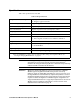
Specifications Table 1 lists specifications for the M2. Table 1: M2 Specifications Target Gas/Detection Range Hydrogen Sulfide: 0 - 100 ppm, 1 ppm increments Alarm Settings (Alarm 1/Alarm 2) 10 ppm/50 ppm* Construction (housing) Explosion-proof Junction Box, NEMA 4 Area Classification Explosion-proof for Class I, Groups B, C, and D Sampling Method Diffusion Input Power 19 - 30 VDC Controls • Three push button switches • Three magnetic switches for non-intrusive calibration Weight 5.5 lbs.
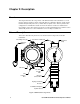
Chapter 2: Description Overview This chapter describes the components of the M2 transmitter. The transmitter is a 4 - 20 mA type detector head. It consists of the H2S detector, calibration adapter/splash guard, terminal PCB, the M2 junction box, and the detector junction box. The two junction box configuration is intended for situations where the detector needs to be installed at an inaccessible location.
M2 Junction Box The M2’s cast aluminum junction box protects the terminal PCB and wiring connections made to the terminal PCB. Use the top 3/4’’ conduit hub to connect wiring from the terminal PCB to external power and/or to an external device, typically an RKI controller. Use the bottom 3/4” conduit hub to wire the remotely installed H2S detector. Use the junction box’s two mounting slots to mount the M2 to a vertical surface at the monitoring site.
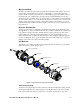
detector housing body. Use these wires to connect the H2S detector to the terminal strip. One of the wires is red and one of the wires is black. The housing includes a four-socket pattern. This socket pattern accepts the sensor’s four pins to secure the sensor within the detector housing. A pre-amplifier, located between the sockets and two interconnect wires, conditions the sensor’s signal before the signal reaches the controller. Housing Cap & Cap Gasket The housing cap screws onto the detector housing.
Internal Description This section describes the internal components of the M2. The internal components of the M2 include the terminal PCB which provides for all the wiring connections to the M2 and the control PCB which displays the gas reading and has the control buttons.
control PCB with a ribbon cable. A 5 position connector on the left side of the terminal PCB is used by factory or field service personnel to program the M2. Power/Signal Terminal Strip The power/signal terminal strip is a three position plug-in style terminal strip located at the top of the left terminal column. It is used to connect 24 VDC power to the M2 and to connect the 4 - 20 mA output signal to a device. The signal output, the S terminal, does not have to be connected for the M2 to function.
Termination Jumper A two pin header with a termination jumper installed is located below the Modbus terminal strip. The jumper has no function unless the M2 is wired into a Modbus installation. See “Chapter 8: RS-485 Modbus Output” on page 37 for a description of using the M2 in a Modbus system. Control PCB The LCD display and control switches are located on the control PCB.
Status LEDs The M2 includes five status LEDs that are located above the display (see Figure 2). • Fail LED The fail LED turns on when the M2 is experiencing a fail condition. A fail condition can be caused by a detector failure or low detector signal. • Alarm 1 LED The alarm 1 LED is on when the M2 is experiencing an alarm 1 condition. • Alarm 2 LED The alarm 2 LED is on when the M2 is experiencing an alarm 2 condition.
Chapter 3: Installation & Startup Overview This chapter describes procedures to mount the M2 Transmitter in the monitoring environment and wire it to input power and devices. Mounting the M2 Transmitter 1. 2. Select a mounting site that is representative of the monitoring environment. Consider the following when you select the mounting site. • For the M2 junction box, select a site where the junction box is not likely to be bumped or disturbed.
Ø3.65 2.70 .38 3/4 Conduit Hub 5.25 Rubber Spacer, 3X H2S Detector 11.40 Max Calibration Adapter/ Splash Guard 1.13 Figure 5: Outline & Mounting Dimensions, Detector Junction Box 3. 11 Install 3/16 inch I.D. flexible polyurethane tubing to the fitting at the bottom of the calibration adapter/splash guard and route it to an accessible area that is close to the M2 junction box. See the “Parts List” on page 47 for available tubing.
Wiring the M2 Transmitter WARNING: Always verify that the power to the M2 is off before you make wiring connections. 1. Confirm that no power is being applied to the M2. 2. Remove the detector junction box’s cover from the junction box. 3. Remove the M2 junction box’s cover from the junction box. 4. Grasp the control PCB by its edges. 5. Gently pull until the control PCB is pulled away from the banana jacks.
CAUTION: If shielded cable is used, leave the cable shield’s drain wire disconnected and insulated at the detector junction box. You will connect the opposite end of the cable’s drain wire to the M2 junction box’s chassis (earth) ground.
NOTE: If the M2 is being wired to a PLC or DCS device, see “Appendix B: PLC and DCS Device Wiring” on page 49, then continue with step 8. Use the following recommendations to determine how to wire the M2: • If Modbus connections will not be used and only the PWR/SIG connections will be used, use a two or three conductor shielded cable or two or three wires in conduit for connections to the power/signal terminal strip depending on whether or not the signal (S) terminal is used.
See Figure 7 below for field wiring connections to the M2. RKI Controller Terminals Alarm Device Power C + TOXIC See Detector Wiring A B RS 485 See Modbus Wiring C NC NO FAIL Alarm 1 Alarm Device C NC NO ALARM 1 (24 VDC) - + OXY 4 - 20 mA In (S) Fail Alarm Device C NC NO ALARM 2 S (24 VDC) + PWR/SIG Cable Shield Alarm 2 Alarm Device Typical Alarm Wiring Shown Figure 7: Wiring the M2 Junction Box to a Controller and Alarm Devices 16.
NOTE: Allow the M2’s detector to warm up for 15 minutes before you continue with the next section, “Adjusting the Fresh Air Reading.” Adjusting the Fresh Air Reading When the M2 is shipped from RKI Instruments, Inc., it is factory calibrated. If a full calibration is desired at startup, see “Calibration” on page 33. Verify that the M2 is in a fresh air environment (environment known to be free of combustible or toxic gas vapors and of normal oxygen content, 20.9%).
17 4. Press and release the ENTER button. The M2 will perform a zero operation and the display will indicate SPAN w/Cal Gas?. 5. Press and release the DOWN/NO button. The display will indicate Leaving CAL Mode and the M2 will return to normal operation.
Chapter 4: Operation Overview This chapter describes the M2 in normal operation. This chapter also describes the M2 in alarm 1, alarm 2, and fail conditions and suggests responses to these conditions. Normal Operation Normal operation is defined as follows: • The start-up procedure is complete. • The M2 is not indicating an alarm 1, alarm 2, or fail condition. • The M2 is not in Calibration, Configuration, or Gas Type modes.
4 - 20 mA Signal Output Operation The output at the S terminal of the power/signal terminal strip is a 4 - 20 mA signal that corresponds to the detection range of the M2. During normal operation, this signal tracks the gas concentration on the LCD. There are several circumstances where the signal output will not track the display reading but will behave as follows: • When the M2 is in its warm-up period, the signal output will be fixed at 3.5 mA (zero).
Table 4: Visual and Audible Alarm Indications Condition Low Power * Cause Visual Indication(s) DC power source less than 18.5 volts. • F LED is on • LowPower message and actual voltage of incoming DC power 1If the M2 is in both an alarm 1 and an alarm 2 condition, both alarm LEDs are on and the display alternates between the gas reading and the ALMS 1&2 message. NOTE: You can select normally energized (N. EN) or normally de-energized (N.
NOTE: If the M2 is in both an alarm 1 and alarm 2 condition, both the A1 and A2 LEDs will be on, the gas reading will alternate with the ALMS 1&2 message, and both alarm relays will energize. Responding to an Alarm 2 Condition 1. Follow your established procedure for a high level toxic gas condition. 2. After the gas reading falls below the alarm 2 setpoint, press the ENTER button to reset the alarm circuit.
NOTE: The low power alarm cannot be cleared using the ENTER button. When the voltage increases to 19.0 volts, the low power alarm is cleared and the M2 will begin its warm-up sequence. Responding to a Low Power Condition 1. Determine and correct the cause of the low power condition. 2. When the input power increases above 19.0 volts, the M2 will begin its warm-up sequence. 3. Verify that the M2 enters normal operation after its warm-up sequence. If necessary, perform a fresh air adjustment.
Chapter 5: Configuration Mode Overview This chapter describes how to view and change M2 parameters using Configuration Mode. It is accessed using the program buttons. Configuration Mode includes a 5-minute time-out feature. If you do not press a control button for 5 minutes, the M2 automatically returns to normal operation. NOTE: If the M2 returns to normal operation because of a time-out, it enters a warmup period just as it does when it is first turned on.
Table 5: Configuration Parameters Parameter (Factory Set Value) Description ALARM-1 (level) (10 ppm) The gas reading at which the M2 initiates an alarm 1 condition. ALARM-1 (activation) (Increase) Indicates if the alarm 1 circuit is activated by gas readings increasing (Increase) or decreasing (Decrease) to the ALARM-1 Level. ALARM-1 (relay action) (N. DE-EN) If set as N. DE-EN, the alarm 1 relay is de-energized in normal operation and energizes when an alarm 1 condition is initiated. If set as N.
Table 5: Configuration Parameters (Continued) Parameter (Factory Set Value) Description ZeroSupp (2 ppm) The zero suppression feature helps prevent “jumpy” readings near the fresh air reading. For example, if the zero suppression is 2.0 ppm, the M2 will display a reading of 0 ppm for gas readings from -2 ppm to 2 ppm. It is settable from 0 to 6% of the detection range. FILTER (5 secs) The filter feature helps “smooth out” jumpy or noisy signals from the detector.
Chapter 6: Gas Type Mode Overview This chapter describes how to use Gas Type Mode to select the M2’s gas type. The gas type determines the target gas and detection range. CAUTION: The target gas is factory set and does not normally need to be changed. The standard setting for the 65-2615RK-05-04 is hydrogen sulfide. Gas Type Mode includes a 5-minute time-out feature. If you do not press a button for 5 minutes, the M2 automatically returns to normal operation.
Table 6: Gas Types Gas Type Choices Detection Range NO 0 - 100 ppm HF 0 - 9.00 ppm HCN 0 - 15.0 ppm HCL 0 - 15.0 ppm H2SE 0 - 5.00 ppm GEH4 0 - 1.50 ppm F2 0 - 3.00 ppm CLO2 0 - 1.00 ppm B2H6 0 - 5.00 ppm ASH3 0 - 1.50 ppm SO2 0 - 6.00 ppm NH3 0 - 200 ppm NH3 0 - 75.0 ppm CL2 0 - 3.00 ppm CL2 0 - 10.0 ppm 4. When the desired target gas is on the display, press and release the ENTER button. The display will ask SAVE IT? YES/NO. 5.
seconds before returning to Configuration Mode. Repeat steps 6 - 8 until the settings are as desired. 9. After the M2 completes its warm-up sequence, the display will indicate CAL NEEDED. Since the gas type has been changed, a successful calibration must be performed before the M2 can enter normal operation. 10. Press and release the UP/YES button to enter Calibration Mode.
Chapter 7: Maintenance Overview This chapter describes procedures for performing preventive maintenance, troubleshooting, calibrating the M2, and replacing field replaceable parts. Preventive Maintenance This section describes a recommended preventive maintenance schedule to ensure the optimum performance of the M2. It includes daily, monthly, and quarterly procedures. Daily Verify a display reading of 0 ppm. Investigate significant changes in the reading.
10. If external alarms have been disabled, enable them when the display returns to a normal fresh air reading. 11. Store the components of the calibration kit in a safe place. Quarterly Calibrate the M2 as described in “Calibration” on page 33. See “Calibration Frequency” on page 32 for a discussion of calibration frequency guidelines. Troubleshooting The troubleshooting guide describes symptoms, probable causes, and recommended action for problems you may encounter with the M2.
Table 7:Troubleshooting the Hydrogen Sulfide Detector (Continued) Condition Symptom(s) Probable Causes Recommended Action Flickering Display The display reading flickers often. • The M2 is experiencing false readings due to RFI or EMI. • The noise filter setting is too low. • The zero suppression setting is too low. • The display screen is malfunctioning. 1. Verify that the M2 wiring is properly shielded. See “Wiring the M2 Transmitter” on page 12. 2.
Calibration Frequency Although there is no particular calibration frequency that is correct for all applications, a calibration frequency of every 3 to 6 months is adequate for most hydrogen sulfide transmitter applications. Unless experience in a particular application dictates otherwise, RKI Instruments, Inc. recommends a calibration frequency of every 3 months.
Calibration This section describes how to calibrate the M2 transmitter. It includes procedures to prepare for calibration, enter Calibration Mode, adjust the fresh air (zero) setting, adjust the span setting, and return to normal operation. WARNING: The M2 is not an active gas monitoring device during the calibration procedure. The 4-20 mA output signal will “freeze” at 3.5 mA and all relays will remain in their non-alarm state while the M2 is in Calibration Mode.
Adjusting the Fresh Air Reading 1. While in normal operation, press and hold the UP/YES button for 5 seconds to enter Calibration Mode. Release the button when the following screen appears. Calib? YES/NO 2. If you want to continue with calibration, press and release the UP/YES button. The display will indicate the target gas and CAL Mode for a few seconds before showing FreshAir Adjust?. If you want to exit Calibration Mode, press and release the DOWN/NO button.
Response Time” on page 32. 5. Turn the regulator knob clockwise to close it. 6. Unscrew the calibration gas cylinder from the fixed flow regulator. The M2 will continue to display the maximum gas response on the display and retain the response level in its memory. 7. Adjust the gas reading up or down to match the calibration gas cylinder concentration by using the UP/YES and DOWN/NO buttons, then press and release the ENTER button. 8. The M2 will perform a span operation.
6. Install the spacer and rubber boot onto the replacement sensor’s face. 7. Carefully plug the replacement sensor into the four-socket pattern that is located in the detector housing. 8. Make sure the cap gasket is in place and screw the detector housing cap back onto the detector housing body. 9. Screw the calibration adapter/splash guard back onto the detector housing cap. 10. Turn on or plug in power to the M2.
Chapter 8: RS-485 Modbus Output Overview This chapter describes the M2’s RS-485 Modbus output and how to configure the M2 to make use of it. It also discusses how to wire the M2 into a Modbus system. The M2 provides an RS-485 serial communications interface. It is a Modbus Slave Device, supporting 2-wire RS-485 Modbus RTU serial communications. Wiring the M2 in a Modbus System The M2 is a 2-wire Modbus RTU device.
NC NO FAIL C NC NO ALARM 1 C NC NO ALARM 2 TOXIC To Additional M2s A B C RS 485 C NC NO ALARM 2 See Detector Wiring A B C RS 485 Input Common D1 Terminals D0 TOXIC See Detector Wiring C S PWR/SIG OXY NC NO FAIL C NC NO ALARM 1 C S PWR/SIG 24 VDC OXY Power Supply Modbus Controller Figure 8: Recommended Modbus Wiring Alternate Modbus Wiring For Existing Installations Although the wiring shown in Figure 8 is recommended, it is possible to wire the M2 into a Modbus system with only 4 wires
Termination Jumper The M2 includes a 2-pin termination header (see Figure 2) that is used when the M2 is used in a Modbus system. Every M2 is supplied with a termination jumper (a jumper block) installed onto this header. If the M2 is not used in a Modbus system, this jumper has no function. When the M2 is installed in a Modbus system, this jumper must be installed in an M2 that is at the end of a Modbus line.
Using the M2 in a 4-wire Modbus System Although the M2 is a 2-wire Modbus RTU device, it can be used with a 4-wire Modbus controller if the system wiring is modified as follows: • Connect the controller’s TxD0 and RxD0 wires together and use this connection as the 2-wire Modbus D0 signal. • Connect the controller’s TxD1 and RxD1 wires together and use this connection as the 2-wire Modbus D1 signal.
Table 9: Configuration Parameters Modbus Mode Parameter Available Settings & Description Enabled/Disabled Can be set to ENABLED or DISABLED (factory setting). Enables or disables the Modbus output. Slave ID The Slave ID can be set to values from 1 (factory setting) to 247. The M2 will only receive messages from the Master which are addressed to this Slave ID (except for broadcast messages which are received by all slaves).
Supported Modbus Functions The M2 supports Function Code 03: Read Holding Registers and Function Code 16: Write Registers. The register assignments detailed below were implemented in M2 firmware version 5.0. Please see revision B of the M2 manual if you have an M2 with a firmware version previous to 5.0. WARNING: Do not attempt to use registers according to the instructions below with units that have firmware versions previous to 5.0. For the Modbus register assignments of M2s with firmware previous to 5.
Table 11: Register 2, Operating State, Alarms & Relays Bit & Field Assignments (Continued) Bit(s) Value [11] Gas Type Change 0=Not Changed 1=Changed [10] Configuration Change 0=Not Changed 1=Changed [9] Calibration Activity Flag 0=No Calibration Activity 1=Calibration Activity Has Occurred [8] Fail Status 0 = Fail Not Asserted 1 = Fail Asserted [7:6] Alarm 2 Status 0 = No Alarm 1 = Unacknowledged Alarm 2 = Acknowledged Alarm 3 = Unused Code [5:4] Alarm 1 Status 0 = No Alarm 1 = Unacknowledged A
Register 12 Register 12 is the range (full scale readout). Register 13 Register 13 is the alarm 1 set point. The decimal point location is the same as specified in Register 1. Register 14 Register 14 is the alarm 2 set point. The decimal point location is the same as specified in Register 1. Registers 15 - 19 Registers 15 - 19 are the Gas Name ASCII String (NULL Terminated). Registers 20 - 22 Registers 20 - 22 are the Gas Units String (NULL Terminated). Register 23 Register 23 is the alarm 1 trigger.
Register 30 Register 30 is the alarm 2 relay reset. 0=Latching 1=Self-Resetting Register 31 Register 31 is the alarm 2 ON delay. Integer values are in seconds. Register 32 Register 32 is the alarm 2 OFF delay. Integer values are in seconds. Register 33 Register 33 is zero suppression. Toxics and LEL: 0%-6% of full scale Oxygen: 0%-0.7% Oxygen The decimal point location is the same as specified in Register 1. Register 34 Register 34 is noise filter. Integer values in seconds. 0-60 in 5 second increments.
14=Operation Not Performed Register 39 Register 39 is the auto-zero disable. 0=AutoZero Enabled 1=AutoZero Disabled Register 40 Register 40 is the remote configuration register access level 0=None 1=Alarm Reset Function Code 16: Write Registers There are 21 registers in Function Code 16 that can be used to write to the M2. This manual only describes Register 16 because it can be used to reset an alarm condition. For a complete description of Function Code 16, request Appendix C from RKI Instruments, Inc.
Parts List Table 13 lists replacement parts and accessories for the M2 Transmitter. Table 13: Parts List Part Number 47 Description 06-1248RK Calibration kit sample tubing (3/16 in. x 5/16 in.
Appendix A: Control Button Quick Reference Guide The M2’s control buttons allow access to operational modes, resetting of alarms, and display of the Information Screen. Table 14 shows which button combinations perform these functions and which parameters are available for adjustment while in the operational modes. While in these modes, display prompts showing a “?” require you to respond by pressing either the UP/YES (for yes) or DOWN/NO (for no) button.
Appendix B: PLC and DCS Device Wiring The M2 can be wired to a PLC or DCS device if desired. 1. Guide multi conductor shielded cable or cables or wires in conduit through the top conduit hub of the junction box. The number of cables or wires needed will depend on whether any relays are used and whether the Modbus output is used.
See Figure 12 below for field wiring connections to the M2.
Appendix C: Function Code 16 Registers The M2 supports Function Code 16 that allows writing to the M2. There are 21 registers in this Function Code. The register assignments detailed below were implemented in M2 firmware version 5.0. Please see revision B of the M2 manual if you have an M2 with a firmware version previous to 5.0. WARNING: Do not attempt to use registers according to the instructions below with units that have firmware versions previous to 5.0.
Register 9 Register 9 is the alarm 2 relay state. 0=Normally De-Energized 1=Normally Energized Register 10 Register 10 is the alarm 2 relay reset. 0=Latching 1=Self-Resetting Register 11 Register 11 is the alarm 2 ON delay. Integer value is in seconds. Register 12 Register 12 is the alarm 2 OFF delay. Integer value is in seconds. Register 13 Register 13 is the zero suppression. Toxics and LEL: 0%-6% Full Scale Oxygen: 0%-0.7% Oxygen Value must be an integer. Any decimals are omitted.
Register 19 Register 19 is for clearing change flags. When parameters are changed at the M2, a flag is raised at the controller. This register can be used to clear those flags. Table 16: Register 19, Clear Change Flags Bit(s) Value & Field [15:2] Unused [1] Write “1” to this bit to clear “Gas Type Changed” flag [0] Write “1” to this bit to clear “Configuration Changed” flag Register 20 Register 20 is the AutoZero Disable.