
User Manual


65-2516RK Oxygen T r a ns mitte r • 5
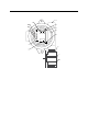
NOTE: The oxygen detector used in this transmitter is normally provided with a Killark
HKB junction box an d an HFC l id rated expl osi on pr oo f fo r Cl ass I, Groups B, C,
and D. This combination is shown in Figure 2 above. Any juncti on box with an
internal volume less than or equal to 69 cubic inches and rated explosion proof
for Class I, Groups B, C, and D may be used for this transmitter as long as the
amplifier w ill f it in it.
2. At the monitoring site, use #10 screws through the junction box’s two mounting holes
to secure the junction box to a vertical surface.
Wiring the Oxygen Transmitter to a Controller
WARNING: Always verify that th e power source is OFF before you make wi ring
connections.
1. Tu rn off the contro ller.
2. Turn off or unplug incoming power to the con troller.
3. Remove the junction box cover.
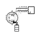
4. Verify that the detector leads are wired to the amplifier’s detector terminal strip.
If necessary, connect the detector leads to the detector terminal strip as shown in
Figure 3.
5. Verify that the jumper block is installed over the Oxygen se lec tor of the am pl ifie r t ype
selector as shown in Figure 3.
6. Guid e a tw o-conductor, shielded cable or two w ires in conduit through the top
conduit hub of the j unction box.
WARNING: To maintain the explosi on proof classification of the oxygen detector/
junction box co mbination, a condu it seal must be used within 18 inches o f
the junction box condui t hub used for wiring to the cont roller.
7. Connect the two wires to the interconnect terminal strip as follow s (s ee Figure 3).
• Connect the positive wire to the terminal labeled 24V +.
• Connect the feedback (or signal) wire to the terminal labeled 4/20 FB.
CAUTION: If using shield ed cable, leave the drain wire insulated and disc onnected at the
transmitter. You will connect the opposite end of the cable’s drain wire at the
controller.
8. Secure the junction box cover to the junctio n bo x.
9. Route the cable or wires leading from the oxygen transmitter through one of the
conduit hubs at the controller housing.
CAUTION: Do not route power and transmitter wiring through the same conduit hub. The
power cable m ay disr upt the t ransmission of the tra nsmitter signa l to the controller.