
User Manual


65-2516RK Oxygen T r a ns mitte r • 3
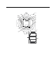
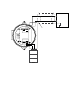
Sensor
The sensor is secured within the sensor housing by the two pins. Through a series of
chemical and electrical reactions, the sensor produces an electrical output that is
proportional to the detector range of the transmitter.
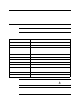
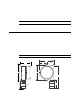
Amplifier
The amplifier converts the electrical output from the sensor to a 4 to 20 mA signal (that is
proportional to the detection range) an d tran smits the signal to a gas monitoring
controller. The amplifier includes the amplifier type selector, detector terminal strip,
interconnect terminal strip, span pot, z ero pot, and test points (see Figure 1).
Amplifier Type Selector
The amplifier type selector is near the bottom left corner of the amplifier. It is to the left of
the detector terminal strip and below the span po t.
The amplifier included with the oxygen transmitter is designed for use with RKI’s oxygen
and toxic gas transmi tters. The amplifier type selector determines for which transm itter
the amplifier is intended . For oxygen transmitters, a jumper block is installed over the
OXYGEN selector (see Figure 1).
Detector Terminal Strip
The detector terminal strip is the four-point terminal st rip near the bottom of the
amplifier. Use the detector termina l strip to connect the oxygen detector to the amplifier.
NOTE: The oxygen detector is factory-wired to the amplifier. See the Installation section
of this manual for all wiring procedures related to the transmitter.
Interconnect Terminal Strip
The interconnect terminal strip is the four-point terminal strip nea r the top of the
amplifier. Use the interconnect terminal strip to co nnect the amplifier to a controller.
Span Po t
The span pot is on the left side of the amplifier. Of the three pots, the span pot is bottom
most. Use the span pot to adjust the transmitter’s fresh air output during the start-up and
calibration procedures.
Zero Pot
The zer o pot is above the span pot. Use the zer o pot to adjust the transmitter’s oxygen-free
output during the calibra tion procedures.
CAUTION: The third potentiometer is factory-set. Do not adjust it.
Test Points
The test points (labeled TP- and TP+) are on the left and right side of the interconnect
terminal strip. The test points produce a 100 to 500 mV output that is proportional to the
transmitter’s 4 to 20 mA output. Use the test points and a voltmeter to mea sure the
transmitter’s output during the start-up and calibration procedures.