
User Manual


2 • 65-2516 RK Oxygen Transmitt er
Description
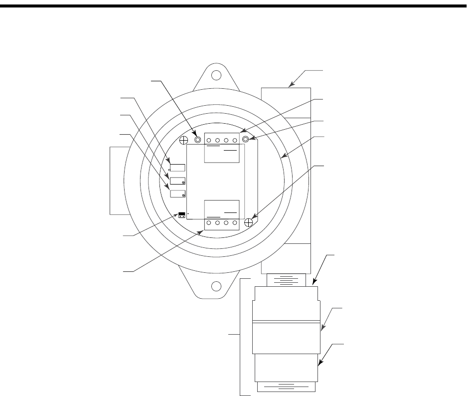
This section describes the components of the oxygen transmitter. The transmitter consists
of the oxygen detecto r, amplifier, and junction box.
Figure 1: Oxygen Transmitter Component Location
Oxygen Detector
The oxygen detector includ es the detector housing and sensor.
Detector Housing
The detector housing protects the sensing components within the housing. Use the
mounting threads at the top of the ho using to screw the oxygen detector into the bot tom
conduit hub of the junct ion box. Use the removable cap near the bottom of the housing to
access the sensor for maintenance or replacement. The cap protects the sensor from
damage an d includ es a flame arres tor wh ich con tains any spa rks wh ich may occu r withi n
the detector housing. A cap gasket seals the interface between the housing and cap. The
flame arrestor guard is permanently bonded to the cap.
Two wires extend from the top of the detector housing. Use these wires to connect the
oxygen detector to the amplifier . The housing includes sockets installed on a circuit board.
These sockets accept the sensor’s tw o pins to secure the sensor within the detector
housing. The circuit board with the sockets conditions the sensor’s signal before the signal
reaches the amplifier.
3/4" NPT Conduit Openin
g
For Wire Entry
ZERO
SPAN
Not
Used
4/20
FB
+
24V
POWER/SIG
OXY
W
G
SENSOR
TP
-
TP
+
Not
Used
OXYGEN
Interconnect Terminal
Strip
Test Point (+)
Amplifier
Securing Screw (2X)
Detector
Housing
Detector Housing
Cap
Flame Arrestor
Guard
Oxygen
Detector
Test Point (-)
Factory Set
Potentiometer
Zero
Potentiometer
Span
Potentiometer
Jumper Block
I
nstalled On Oxygen
Select Header
Detector Terminal
Strip