
User Manual


10 • 65-251 6RK Oxygen Transmitter
Replacing Components of the Oxygen Transmitter
This section includes procedures to replace the oxygen sensor and amplifier. A procedure
to replace the entire detector assembly is at the end of this section. In most cases, it is not
necessary to replace the entire detector assembly.
Replacing the Oxygen Sensor
1. Tu rn off the contro ller.
2. Turn off or unplug incoming power to the con troller.
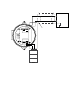
3. Unscrew the detector housing cap from the detector housing.
4. Unplug and remov e the oxygen sensor.
5. Carefully plug the replacement sensor into the socket pattern that is located in the top
section of the detect or housing.
NOTE: Match the sensor’s male pins with the two female sockets as you plug the sensor
into the socket.
6. Screw the detector housing cap onto the detecto r hou sing.
7. Turn on or plug in incoming power to the controller.
8. Turn on the controller.
CAUTION: Allow the replacement sensor to warm up for 5 minutes before you continue with the
next step.
9. Calibrate the replacement sensor as described in the Calibration sectio n of this
manual.
Replacing the Amplifier
1. Tu rn off the contro ller.
2. Turn off or unplug incoming power to the con troller.
3. Remove the junction box cover.
4. Disconnect the detector leads from the detector termina l strip.
5. Unscrew and remove the two screws that secure the amplifier to the junction box.
The screws are at the top left and bottom right of the amplifier.
6. Remove the am plifier.
7. Place the new amplifier in the same position as the old amplifier.
8. Use the two screws you removed in step 5 to secure the new amplifier to the junction
box.
9. Verify that the jumper block is installed over the OXYGEN selec t or of th e am plifier
type selector as shown in Figure 3.