
User Manual


8 • 65-2516 RK Oxygen Transmitt er
12. Turn the regulator’s on/o ff knob clockwise to close it.
13. Unscrew the calibration cup from the detector.
14. Unscrew the regulator from the zero air calibration cylinder. For convenience, leave
the sample tubing con nected to the regulator and the calibration cup.
15. S t ore t he compon ents of the calibration kit in a saf e and conven ient pl ace.
16. Remove the voltmeter leads from the test points.
17. Secure the junction box cover to the junction bo x.
Maintenance
This section describes maintenance procedures. It includes preventive maintenance,
troubleshooting, and component replacement procedures.
Preventive Maintenance
This section describes a preventive maintenance schedule to ensure the optimum
performance of the oxygen transmitter. It includes daily, mo nthly, and quarterly
procedures.
Daily
Verify a display reading of 20.9% oxygen at the co ntroller. Investigate significa nt changes
in the reading.
Monthly
This procedure describes a test to verify that the oxygen transmitter responds properly to
oxygen deficiency.
NOTE: Performing a response test on the oxy gen tra ns mitter may cause alarms. Be sure
to put the controller into its calibration pr ogram or disable ext ernal alarm s befor e
performing this test.
Prepari ng for the respon se test
1. Verify that the display reading for the channel you are testing is 20.9% oxygen.
If the display reading is not 20.9% oxygen, set the fresh air reading of the transmitter
as described in “Sta rt Up” on page 7 of this manual, then conti n ue this pr o c edure.
2. Set a voltmeter to measure in the millivolt (mV) range.
WARNING: Do not remove the detector housi ng cap or junctio n bo x cover while the
circuits are energized unless the area is determined to be non-hazardous.
Keep the detector housing cap an d ju nction box cover tightly cl osed during
operation.
3. Remove the junction box cover, then plug the voltmeter leads into th e tes t points on
the amplifier. Pl ug the positive lead into th e test point labeled TP+; plug the negative
lead into the test point labeled TP-.
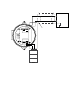
Performing the response test
1. Exhale into th e bottom of the oxygen detect or.
2. Stop exhaling into the bottom of the detector, then verify that the reading on the