
User guide

65-2515RK Oxygen Detector • 11
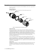
7. Unscrew the regulator from the cylinder.
8. Remove the calibration cup from the detector. For convenience, leave the calibration
cup and regulator connected by the sample tubing.
Returning to Normal Operation
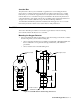
1. Allow about 45 seconds for the oxygen reading to increase above the decreasing alarm
point and return the controller to normal operation.
NOTE: If you do not allow the oxygen reading to increase above the decreasing alarm
point, then unwanted alarms may occur.
2. Verify that the controller display reading increases and stabilizes at 20.9% oxygen.
3. Store the components of the calibration kit in a safe and convenient place.
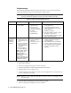
Parts List
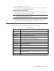
Table 3 lists replacement parts and accessories for the oxygen detector.
Table 3: Parts List
Part Number Description
06-1248RK Sample tubing (3/16 in. x 5/16 in.; specify length when ordering)
18-0400RK-01 Junction box with spacers
65-1025RK Oxygen replacement sensor, plug-in
65-2514RK Oxygen replacement detector assembly (includes plug-in sensor),
CSA classified (does not include junction box)
65-2515RK Oxygen detector/junction box, CSA classified
71-0137RK 65-2515RK Oxygen Detector Operator’s Manual (this document)
81-F301RK-LV Calibration kit (34 liter)
81-0076RK-01 Zero air calibration cylinder (34 liter)
81-0078RK Calibration cylinder (100% nitrogen, 17-liter)
81-0078RK-01 Calibration cylinder (100% nitrogen; 34-liter)
81-1050RK Regulator with gauge and knob, 0.5 LPM, for 17- and 34-liter steel
calibration cylinders
81-1117RK Calibration cup