
User Manual


2 • 65-2502 RK/65-2510RK Oxygen Detect or
Description
This section describes the components of the oxygen detector. The detector includes the
oxygen cell, detector housing, and detector connector. This section also describes the
junction box.
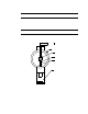
Oxygen Detector
The sensing components of the detector are encapsulated within a conduit mounting
black anodized al u min um ho u sin g. Through a series of ch emi c al an d el ect ron ic react io ns ,
the detector produces a millivolt output that is proportion al to the detection ra nge. 3/4”
NPT mounting threads at the top of the detector allow you to mount the detector to the
junction box or a 3/4 ” NPT conduit fitting. Two co lor-coded leads extend from the top of
the detector. The leads allow you to connect the detector to a con troller.
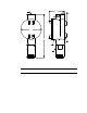
Junction Box
The junction box allows yo u to install the oxygen detector at a mounting site that is
remote from a controller, and it protects the detector wiring connections. Two conduit
hubs allow you to mount the oxygen detector to the junction box and connect the wiring
from the detector to a controller. Three spacers installed on the back of the junction box
control the distance of the junction box from a mounting surface and ensure that there is
enough room to instal l a calibration cup on th e detector during calib ration.
A terminal block within the junc tion box facilitates the wiring process. A cover on the
front of the junction box allo ws access to the interior of th e jun ction box.
Installation
This section d e scribe s procedures to mount the oxygen detecto r in the monitoring
environment and wire the detector to a controller.
Mounting the Oxygen Detector
NOTE: If you are mounting a 65-2510RK, it does not include a junction box and is
usually factor y installed in one of a controller’s conduit hubs or may be field
installed using the 3/4” NPT threads on the end with the wires.
1. Select a mounting site that is repres entative of the monitoring environment. Consider
the following when you select the mounting site.
• Select a site wher e the detector is not likely to be bumped or disturbed. Ma ke sur e
there is sufficient room to perform start-up, maintenance, and calibration
procedures.
• Select a site that is at normal breathing level.