65-2496RK/65-2499RK Carbon Monoxide Detector Operator’s Manual Part Number: 71-0156RK Revision: 0 Released: 2/16/11 www.rkiinstruments.
WARNING Read and understand this instruction manual before operating detector. Improper use of the detector could result in bodily harm or death. Periodic calibration and maintenance of the detector is essential for proper operation and correct readings. Please calibrate and maintain this detector regularly! Frequency of calibration depends upon the type of use you have and the sensor types.
Product Warranty RKI Instruments, Inc. warrants gas alarm equipment sold by us to be free from defects in materials, workmanship, and performance for a period of one year from date of shipment from RKI Instruments, Inc. Any parts found defective within that period will be repaired or replaced, at our option, free of charge.
Table of Contents Overview . . . . . . . . . . . . . . . . . . . . . . . . . . . . . . . . . . . . . . . . . . . . . . . . . . . . . . . . . . . . . . . . . . . 1 Specifications. . . . . . . . . . . . . . . . . . . . . . . . . . . . . . . . . . . . . . . . . . . . . . . . . . . . . . . . . . . . . . . . 1 Description . . . . . . . . . . . . . . . . . . . . . . . . . . . . . . . . . . . . . . . . . . . . . . . . . . . . . . . . . . . . . . . . . . 2 65-2496RK CO Detector . . . . . . . . . . . . . . . . . . .
Overview This manual describes the 65-2499RK carbon monoxide (CO) detector. This manual also describes how to install, start up, maintain, and calibrate the CO detector when used with a gas monitoring controller. A parts list at the end of this manual lists replacement parts and accessories for the CO detector. The 65-2499RK CO detector includes the 65-2496K CO detector and a junction box.
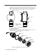
Description This section describes the components of the 65-2496RK and 65-2499RK detectors. The 652499RK includes the 65-2496RK CO detector and a junction box. A two point terminal strip is provided inside the junction box for detector connections. The 65-2496RK does not include a junction box. Figure 1 below shows the components of the 65-2499RK. 3/4 NPT Conduit Hub Junction Box Rubber Spacer, 3X CO Detector Note: There is a two point terminal strip inside the junction box for detector connections.
Detector Housing Body The detector housing body protects the electronic components within the housing. Use the mounting threads at the top of the housing to screw the CO detector into a 3/4” NPT hub. Two wires extend from the top of the detector housing body. Use these wires to connect the detector to a controller. One of the wires is black and one of the wires is red. The housing body includes a four-socket pattern at the bottom of the housing body. The plug-in sensor mates to this socket pattern.
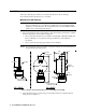
Installation This section describes procedures to mount the CO detector in the monitoring environment and wire the detector to a controller. Mounting the CO Detector NOTE: If you are installing a 65-2496RK, it does not include a junction box and is usually factory installed in one of a controller’s conduit hubs or may be field installed using the 3/4” NPT threads on the end with the wires. The 65-2499RK includes a junction box as shown in Figure 3 below. 1.
Wiring the CO Detector to a Controller WARNING: Always verify that power to the controller is OFF before you make wiring connections. 1. Turn off the controller. 2. Turn off or unplug power to the controller. 3. If the detector is mounted remotely from a controller using the junction box, proceed to step 4. If the detector is mounted directly to a controller, it is normally factory wired.
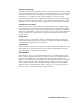
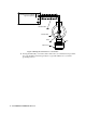
Controller Detector Terminals, + Typical Designations S Controller Housing Shielded Cable Terminal Strip Black Red CO Detector Figure 4: Wiring the CO Detector to a Controller 10. If using shielded cable, connect the cable’s drain wire to an available chassis ground at the controller. RKI controllers typically have a ground stud that is a convenient grounding location.
Start Up This section describes procedures to start up the CO detector and place the detector into normal operation. Introducing Incoming Power 1. Complete the installation procedures described earlier in this manual. 2. Verify that the power wiring to the controller is correct and secure. Refer to the controller operator’s manual. 3. Turn on or plug in the incoming power, then turn on the controller. 4. Verify that the controller is on and operating properly.
Maintenance This section describes maintenance procedures. It includes preventive maintenance, troubleshooting, and component replacement procedures. Preventive Maintenance This section describes a preventive maintenance schedule to ensure the optimum performance of the CO detector. It includes daily, monthly, and quarterly procedures. Daily Verify a display reading of 0 ppm at the controller. Investigate significant changes in the display reading.
5. Unscrew the calibration cup from the CO detector. Make sure that you do not loosen the detector housing cap when you unscrew the calibration cup. 6. When the controller display reading falls below the alarm setpoints, return the controller to normal operation. Quarterly Calibrate the CO detector as described in “Calibration” on page 13. Troubleshooting The troubleshooting guide describes symptoms, probable causes, and recommended action for problems you may encounter with the CO detector.
Probable causes • The plug-in sensor has been replaced and the shorting jumper has not been removed. • The calibration cylinder is low, out-dated, or defective. • The incorrect calibration cup or regulator is being used. • The membrane on the detector housing cap is blocked with dirt or some other particulate contamination. • The detector is malfunctioning. Recommended action 1. Confirm that the shorting jumper on the plug-in sensor pins has been removed. 2.
2. Turn off or unplug power to the controller. 3. Unscrew the detector housing cap from the detector housing body. 4. Unplug and remove the old CO sensor with the boot and charcoal filter attached. 5. Remove the rubber boot and charcoal filter from the old CO sensor. 6. Remove the replacement CO sensor from its packaging and remove the wire jumper that is shorting the WE and RE sensor pins.
12. Turn on the controller. Replacing the Hydrophobic Membrane 1. Turn off the controller. 2. Turn off or unplug incoming power to the controller. 3. Unscrew the detector housing cap from the detector housing body. 4. Gently pry up the edge of the white hydrophobic membrane with a small flat blade screwdriver or a similar tool. 5. Peel off the hydrophobic membrane. It may be necessary to clean off the detector housing cap face to remove any residue left from the adhesive backed membrane. 6.
8. If the detector is installed remotely from a controller in a junction box, reinstall the junction box cover. 9. Turn on or plug in power to the controller. 10. Turn on the controller. CAUTION: Allow the replacement detector to warm up for 5 minutes before you continue with the next step. 11. Calibrate the replacement detector as described in “Calibration” on page 13.
Setting the Zero (Fresh Air) Reading 1. Follow the instructions in the controller operator’s manual for setting the zero reading. 2. When the instructions call for applying zero air to the detector, turn the regulator’s on/off knob counterclockwise to open it. Gas will begin to flow. 3. Allow the gas to flow for two minutes. 4. Set the fresh air reading according to the controller operator’s manual. 5. Turn the regulator’s on/off knob clockwise to close it. 6.
Parts List Table 2 lists replacement parts and accessories for the CO detector.