
Instruction Manual

65-2495RK/65-2498RK H
2
S Detector • 16
the detector housing cap when you unscrew the calibration cup.
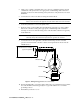
NOTE: For convenience, leave the regulator and calibration cup connected by the
sample tubing.
9. Allow about 45 seconds for the gas reading to decrease below the alarm points and
then return the controller to normal operation.
NOTE: If you do not allow the gas reading to decrease below the alarm points, then
unwanted alarms may occur.
10. Verify that the controller display reading decreases and stabilizes at 0 ppm.
11. Store the components of the calibration kit in a safe and convenient place.
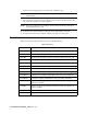
Parts List
Table 2 lists replacement parts and accessories for the H
2
S detector.
Table 2: Parts List
Part Number Description
06-1248RK-03 3 foot length of sample tubing for the calibration kit
07-0039RK Detector housing cap gasket
33-0157RK Hydrophobic membrane, adhesive backed, for detector housing cap
65-2495RK H
2
S replacement detector assembly (includes sensor)
71-0155RK 65-2495RK/65-2498RK H
2
S Detector Operator’s Manual (this document)
81-0076RK Zero air calibration cylinder, 17 liter steel
81-0076RK-01 Zero air calibration cylinder, 34 liter steel
81-0076RK-03 Zero air calibration cylinder, 103 liter steel
81-0151RK-02 Calibration gas cylinder, 25 ppm H
2
S in nitrogen, 58 liter aluminum
81-0151RK-04 Calibration cylinder, 25 PPM H
2
S in nitrogen, 34 liter aluminum
81-1050RK Regulator with gauge and knob, 0.5 LPM, for 17 liter and 34 liter steel
calibration cylinders
81-1051RK Regulator with gauge and knob, 0.5 LPM, for 34AL/58/103 liter cali-
bration cylinders
81-1117RK Calibration cup
ES-1537-H2S H
2
S replacement plug-in sensor