
User Manual

20 • 65-2485RK-02 Multi Point Detector
Returning to Normal Operation
1. Unscrew the calibration cup from the oxygen detector.
NOTE: For convenience, leave regulator and calibration cup connected by the sample
tubing.
2. When the controller display reading rises above the alarm points, return the
controller to normal operation.
NOTE: If you do not allow the gas reading to rise above the alarm points, then unwanted
alarms may occur.
3. Verify that the controller display reading increases and stabilizes at 20.9% oxygen.
4. Store the components of the calibration kit in a safe and convenient place.
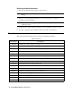
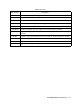
Parts List
Table 5 lists replacement parts and accessories for the multi-point detector.
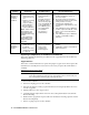
Table 3: Parts List
Part Number Description
06-1248RK-03 Calibration kit sample tubing, 3 ft. length
07-0033RK Detector housing cap gasket (for H
2
S, O
2
and CO detectors)
07-0203RK Rubber retaining boot (for CO and H
2
S detectors)
14-2101RK Spacer between H
2
S sensor and rubber boot
33-7101RK Charcoal filter disk (for CO detector)
65-1025RK Oxygen replacement plug-in sensor
65-2423RK-05 H
2
S replacement detector assembly (includes sensor)
65-2433RK-05 CO replacement detector assembly (includes sensor)
65-2485RK-02 Multi-point detector assembly, O
2
/H
2
S/CO
65-2514RK Oxygen replacement detector assembly (includes sensor)
71-0237RK 65-2485RK-02 Multi Point Detector Operator’s Manual (this document)
81-0064RK-01 Calibration cylinder, 50 ppm CO in air, 34 liter steel
81-0064RK-03 Calibration cylinder, 50 ppm CO in air, 103 liter steel
81-0076RK Zero air calibration cylinder, 17 liter steel
81-0076RK-01 Zero air calibration cylinder, 34 liter steel
81-0076RK-03 Zero air calibration cylinder, 103 liter steel