65-2484RK Multi Point Detector Operator’s Manual Part Number: 71-0252RK Revision: 0 Released: 7/18/14 RKI Instruments, Inc. www.rkiinstruments.
WARNING Read and understand this instruction manual before operating detector. Improper use of the detector could result in bodily harm or death. Periodic calibration and maintenance of the detector is essential for proper operation and correct readings. Please calibrate and maintain this detector regularly! Frequency of calibration depends upon the type of use you have and the sensor types.
Product Warranty RKI Instruments, Inc. warrants gas alarm equipment sold by us to be free from defects in materials, workmanship, and performance for a period of one year from date of shipment from RKI Instruments, Inc. Any parts found defective within that period will be repaired or replaced, at our option, free of charge.
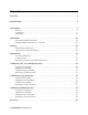
Table of Contents Overview . . . . . . . . . . . . . . . . . . . . . . . . . . . . . . . . . . . . . . . . . . . . . . . . . . . . . . . . . . . . . . . . . . . 1 Specifications. . . . . . . . . . . . . . . . . . . . . . . . . . . . . . . . . . . . . . . . . . . . . . . . . . . . . . . . . . . . . . . . 1 Description . . . . . . . . . . . . . . . . . . . . . . . . . . . . . . . . . . . . . . . . . . . . . . . . . . . . . . . . . . . . . . . . . . 4 Detectors. . . . . . . . . . . . . . . . . . . . . . . . .
Overview This manual describes the 65-2484RK multi point direct connect detector. This manual also describes how to install, start up, maintain, and calibrate the detector when it is used with a gas monitoring controller. A parts list at the end of this manual lists replacement parts and accessories for the detector. Specifications WARNING: Do not use this product in a manner not specified in this instruction manual. Table 1 lists specifications for the multi-point detector.
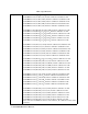
Table 1: Specifications Target Gas 65-2484RK-01: LEL/O2/H2S/AsH3, methane calibration standard for LEL 65-2484RK-02: LEL/O2/H2S/Cl2, methane calibration standard for LEL 65-2484RK-03: LEL/O2/H2S/HCN, methane calibration standard for LEL 65-2484RK-04: LEL/O2/H2S/NH3, methane calibration standard for LEL 65-2484RK-05: LEL/O2/H2S/PH3, methane calibration standard for LEL 65-2484RK-06: LEL/O2/H2S/SO2, methane calibration standard for LEL 65-2484RK-11: LEL (IR CH4)/O2/H2S/AsH3, methane calibration for LEL 65-24
Table 1: Specifications Sampling Method Diffusion Detection Range LEL: 0 to 100 %LEL (lower explosive limit) O2: 0 to 25 %volume CO: 0 to 300 ppm (parts per million) H2S: 0 to 100 ppm (parts per million) AsH3: 0 - 1.50 ppm Cl2: 0 - 3.00 ppm HCN: 0 - 15.0 ppm NH3: 0 - 75.0 ppm PH3: 0 - 1.00 ppm SO2: 0 - 6.
Description This section describes the multi-point detector. It consists of the detectors, the terminal strips, the conduit seal, and the junction boxes. Detectors This section describes the components of the various detectors that are used with each model of the 65-2484RK. 61-0140RK LEL Detector LEL Detector Figure 1: 61-0140RK LEL Detector Component Location The combustible gas detector is a catalytic type detector that produces an electrical output that corresponds to the detection range.
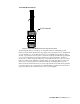
61-0190RK IR LEL Detector IR LEL Detector Figure 2: 61-0190RK IR LEL Detector Component Location The infrared LEL detector is made up of a miniature infrared combustible gas LEL detector housed and encapsulated in a pipe nipple. The pipe nipple has 3/4” NPT threads on each end and a 1 1/4” hex that allows removal or installation of the detector with a wrench.
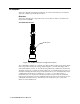
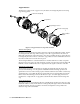
Oxygen Detector The detector consists of the oxygen sensor, the detector housing body, detector housing cap, and cap gasket. Detector Housing Body Cap Gasket Plug-in Oxygen Sensor Detector Housing Cap Flame Arrestor Guard Figure 3: Oxygen Detector Component Location Detector Housing Body The detector housing body protects the electronic components within the housing. Use the mounting threads at the top of the housing to screw the oxygen detector into the 3/4” NPT hub on the bottom of the junction box.
H2S Detector The detector consists of the detector housing body, detector housing cap, cap gasket, rubber boot, spacer, and H2S sensor. Detector Housing Body Cap Gasket H2S Plug-in Sensor Spacer Rubber Boot Detector Housing Cap Flame Arrestor Guard Figure 5: H2S Detector Component Location Detector Housing, Housing Cap, & Cap Gasket The detector housing protects the sensing components within the housing. Use the mounting threads at the top of the housing to screw the H2S detector into a 3/4” NPT hub.
CO Detector The detector consists of the CO sensor, charcoal filter with rubber boot, detector housing body, detector housing cap, and cap gasket. Detector Housing Body Cap Gasket Plug-In CO Sensor Rubber Boot With Charcoal Filter Detector Housing Cap Flame Arrestor Guard Figure 4: CO Detector Component Location Detector Housing, Housing Cap, & Cap Gasket The detector housing body protects the sensing components within the housing.
ESM-01 Detector The ESM-01 detector consists of the detector housing body, detector housing cap, splashguard, cap gasket, and the plug-in sensor. Detector Housing Body Cap Gasket Plug-In SO2 Sensor Detector Housing Cap Splash Guard (removable) Figure 6: ESM-01 Toxic Detector Component Location Detector Housing Body The detector housing body protects the electronic components within the housing. Use the mounting threads at the top of the housing to screw the toxic detector into a 3/4” NPT hub.
Junction Boxes Use the junction boxes to install the multi-point detector at a mounting site that is remote from the controller. The junction boxes protect the terminal strips and wiring connections made to the terminal strips. Use the top 3/4’’ conduit hub to connect wiring from the terminal strips to the controller. Use the cover on the front of the junction boxes to access the interior of the junction boxes. The detectors and terminal strips are factory installed in the junction boxes.
.20 DIA X .45 Slot, (2X), mounting 7.50 3.15 2.40 3/4 NPT Hubs (4X) 3.11 .25 1.25 19.0 Max. CO or H2S Detector Sealed W ire Conduit ESM-01 Detector 3/4" NPT Nipple (2X) LEL Detector Oxygen or C O 3.0 Detector 7.6 Figure 7: Outline & Mounting Dimensions for Versions with Catalytic LEL Detector (65-2484RK-0X, 65-2484RK-2X, 65-2484RK-4X) 3.0 1.
.20 DIA X .45 S lot, (2X), mounting 7.50 3.15 2.40 3/4 NPT Hubs (4X) 3.11 .25 1.25 19.0 Max. CO or H2S Detector Sealed W ire Conduit ESM-01 Detector 3/4" NPT Nipple (2X) IR LEL Detector 3.0 3.0 Oxygen or C O Detector 7.6 Figure 8: Outline & Mounting Dimensions for Versions with IR LEL Detector (65-2484RK-1X, 65-2484RK-3X, 65-2484RK-5X) 2. 1.10 At the mounting site you select, use #10 screws to mount the detector to a vertical surface.
Wiring the Multi-Point Detector to a Controller WARNING: Always verify that the power source is OFF before you make wiring connections. 1. Turn off the controller. 2. Turn off or unplug power to the controller. 3. Remove the junction box cover from the top junction box. 4. Guide a ten-conductor, shielded cable, or ten wires in conduit through the top conduit hub of the junction box. Use appropriate conduit fittings and construction technique for the environmental rating of the junction box.
R ED H 2S B LK B LK L EL GR N B LK W HT (+) S EE T AB LE R ED W HT CON T ROLL ER T ERMI NALS ES M-01 OXY GR N CON T ROLL ER T ERMI NALS R ED B L AC K B LAC K (+) S EE T AB LE G as T ype T able G as T ype + W ire R ED GR EE N AsH3 Cl2 HCN NH3 PH3 SO2 W HIT E GR EE N W HIT E B LAC K H2S D ETEC TO R ESM -01 D ETEC T OR R ED W HITE GR EE N B LAC K W HITE GR EE N W HITE R ED W HITE GR EE N GR EE N B LAC K LEL D ET ECT OR OXYGEN D ETEC T OR Figure 9: Wiring for Catalytic LEL/O2/H2S/ES
R ED CO B LK BLK LEL GR N B LK W HT (+) S EE TAB L E R ED W HT CON T ROLL ER T ERMI NALS ES M-01 OXY GR N CON T ROLL ER T ERMI NALS R ED B LAC K B L AC K (+) S EE TAB LE G as T ype Table G as T ype + W ire R ED GR EE N AsH3 Cl2 HCN NH3 PH3 SO2 W HITE GR EE N W HIT E B L AC K brown yellow white red green blue CO D ETEC T OR ESM -01 D ETEC T OR R ED W HIT E GR EE N B LAC K W HIT E GR EE N W HIT E R ED W HITE GR EE N GR EE N B L AC K LEL D ET ECT OR OXYGEN D ETEC T OR Figure 10: W
R ED H 2S B LK B LK LEL GR N B LK W HT (+) S EE TAB LE R ED R ED CON T ROLL ER T ERMI NALS ES M-01 CO B LK CON T ROLL ER T ERMINALS R ED B LAC K B L AC K (+) S EE TAB LE G as T ype T able G as T ype + W ire R ED B LAC K AsH3 Cl2 HCN NH3 PH3 SO2 W HITE GR EE N R ED B LAC K H2S D ETEC TO R ESM -01 D ETEC T OR R ED W HITE GR EE N B L AC K R ED B LAC K R ED R ED W HIT E B LAC K GR EE N B LAC K LEL D ET ECT OR CO D ETEC T OR Figure 11: Wiring for LEL/CO/H2S/ESM-01 Versions (65-2484RK
R ED H 2S B LK BLK IR L EL GR N B LK W HT (+) S EE TAB LE R ED ES M-01 W HT CON T ROLL ER T ERMINALS GR N OXY CON T ROLL ER T ERMI NALS R ED B LAC K B LAC K (+) S EE TAB LE G as T ype T able R ED G as T ype + W ire GR EE N AsH3 Cl2 HCN NH3 PH3 SO2 W HITE GR EE N W HIT E B LAC K brown yellow white red green blue H2S D ETEC TO R ESM -01 D ETEC T OR R ED W HITE GR EE N B LAC K W HIT E GR EE N W HITE R ED W HITE GR EE N GR EE N B LAC K I R L EL DE TEC TOR OXYGEN D ETEC T OR Figure
R ED CO BLK B LK IR L EL GR N BLK W HT (+) S EE TAB LE R ED ES M-01 W HT CON T ROLL ER T ERMI NALS GR N OXY CON T ROLL ER T ERMI NALS R ED B LAC K B L AC K (+) S EE TAB L E G as T ype T able R ED G as T ype + W ire GR EE N AsH3 Cl2 HCN NH3 PH3 SO2 W HITE GR EE N W HITE B LAC K CO D ETEC T OR ESM -01 D ETEC T OR R ED W HITE GR EE N B L AC K W HITE GR EE N W HITE R ED W HITE GR EE N GR EE N B LAC K IR L EL DE TEC TOR OXYGEN D ETEC T OR Figure 13: Wiring for IR LEL/O2/CO/ESM-01 Ve
R ED H 2S B LK BLK IR L EL GR N B LK W HT (+) S EE TAB LE R ED R ED CON T ROLL ER T ERMI NALS ES M-01 CO B LK CON T ROLL ER T ERMI NALS R ED B LAC K B LAC K (+) S EE TAB LE G as T ype T able G as T ype + W ire R ED B LAC K AsH3 Cl2 HCN NH3 PH3 SO2 W HITE GR EE N R ED B LAC K brown yellow white red green blue H2S D ETEC TO R ESM -01 D ETEC T OR R ED W HITE GR EE N B LAC K R ED B LAC K R ED R ED W HITE B LAC K GR EE N B LAC K I R L EL DE TEC TOR CO D ETEC T OR Figure 14: Wiring f
9. Connect the cable’s drain wire to an available chassis ground at the controller. RKI controllers typically have a ground stud that can be used to ground the cable’s drain wire. Start Up This section describes procedures to start up the multi-point detector and place the detector into normal operation. Introducing Incoming Power 1. Complete the installation procedures described earlier in this manual. 2. Verify that the power wiring to the controller is correct and secure.
Maintenance This section describes maintenance procedures. It includes preventive maintenance, troubleshooting, and component replacement procedures. Preventive Maintenance This section describes a preventive maintenance schedule to ensure the optimum performance of the multi-point detector. It includes daily, monthly, and quarterly procedures. Daily At the controller, verify a display reading of: • 0 %LEL for combustible gas • 20.
NOTE: Ensure that you are using an appropriate calibration cylinder for the channel you are testing. 5. Use the calibration kit sample tubing to connect the regulator to the calibration cup. If you are testing the ESM-01 toxic detector, check the bottom of the calibration cup to see if it has a specified flow direction through the cup and if it does, makes sure you connect the tube from the regulator to the inlet port.
Troubleshooting The troubleshooting guide describes symptoms, probable causes, and recommended action for problems you may encounter with the multi-point detector. NOTE: This troubleshooting guide describes multi-point detector problems only. See the controller operator’s manual for problems you may encounter with the controller. Table 2: Troubleshooting the Multi-Point Detector Condition Symptom(s) Probable Causes Recommended Action Fail Condition Controller indicates a fail condition.
Replacing Components of the Multi-Point Detector This section includes maintenance procedures for the LEL detector, the oxygen detector, the CO detector, the H2S detector, and the ESM-01 detector. Replacing the LEL Detector 1. Turn off the controller. 2. Turn off or unplug incoming power to the controller. 3. Remove the junction box cover from the bottom junction box. 4. Disconnect the detector leads from the terminal block in the junction box.
detector housing body. 7. Turn on or plug in power to the controller. 8. Turn on the controller and place into normal operation. CAUTION: Allow the replacement sensor to warm up for 5 minutes before you continue with the next step. 9. Calibrate the detector as described in “Calibration, O2 Detector” on page 32. Replacing the Oxygen Detector NOTE: In most cases, it is only necessary to replace the oxygen sensor. 1. Turn off the controller. 2. Turn off or unplug incoming power to the controller. 3.
3. Unscrew the detector housing cap from the detector housing body. Make sure not to lose the cap gasket. 4. Unplug and remove the H2S sensor with the rubber boot and spacer attached. 5. Remove the rubber boot and spacer from the old sensor. 6. Install the spacer and rubber boot onto the replacement sensor’s face. 7. Carefully plug the replacement sensor into the socket pattern that is located in the detector housing. 8.
CO Detector This section includes a procedure to replace the plug-in sensor, one to replace the charcoal filter, and one to replace the entire detector assembly. In most cases it is not necessary to replace the entire detector assembly. Replacing the Plug-In CO Sensor CAUTION: The sensor contains electrolyte which is a dilute acid. Do not disassemble the sensor when replacing it with a new one. If sensor electrolyte comes in contact with your skin, wash affected area thoroughly with soap and water. 1.
Replacing the CO Detector NOTE: In most cases, it is only necessary to replace the CO sensor. 1. Turn off the controller. 2. Turn off or unplug power to the controller. 3. Remove the junction box cover from the top or bottom junction box, depending on where your CO detector is installed. Refer to Figures 9 - 14 for CO detector location. 4. Disconnect the detector leads from the terminal block in the junction box. Note the position of the color-coded leads as you remove them. 5.
WARNING: You must replace the plug-in sensor with the same type of sensor that is installed. A detector cannot be converted from one type of detector to another by using a different plug-in sensor. For example, if you are replacing an SO2 sensor, you must replace it with an SO2 sensor. 6. Make sure the cap gasket is in place and screw the detector housing cap with the splashguard back onto the detector housing body. 7. Turn on power to the controller. 8. Turn on the controller.
Calibration Frequency Although there is no particular calibration frequency that is correct for all applications, a calibration frequency of every 3 months is adequate for most multi-point detector applications. Unless experience in a particular application dictates otherwise, RKI Instruments, Inc. recommends a calibration frequency of every 3 months for the catalytic LEL, oxygen, H2S, CO, and ESM-01 detectors and every 6 months for the infrared LEL detector.
for instructions to enter the calibration program. NOTE: RKI controllers have a minimum hold feature for zero adjustment and a peak hold feature for span adjustment. Because of this, the instructions call for turning off the gas to a detector before making adjustments. Setting the Zero Reading 1. Follow the directions in the controller operator’s manual for setting the zero reading. 2.
• 4. 0 ppm for H2S or CO Store the components of the calibration kit in a safe and convenient place. Calibration, O2 Detector This section describes how to calibrate the oxygen detector on the multi-point detector. It includes procedures to prepare for calibration, set the fresh air reading, set the zero reading, and return to normal operation.
6. Unscrew the regulator from the zero air calibration cylinder. Leave the sample tubing connected to the regulator and the calibration cup. Setting the Zero Reading 1. Screw the regulator into the 100% nitrogen calibration gas cylinder. Make sure the regulator is off. It is off when the on/off knob is turned all the way clockwise. 2. Follow the directions in the controller operator’s manual for setting the zero reading. 3.
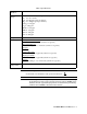
Detector Type Required Calibration Cup Required Regulator/ Flowrate for Calibration Gas Flow Direction Specified on Calibration Cup Ammonia (NH3) 81-1138RK-NH3 81-1051RK-25, 0.25 LPM No Phosphine (PH3) 81-1138RK 81-1051RK, 0.5 LPM Yes Sulphur Dioxide (SO2) 81-1138RK 81-1051RK, 0.5 LPM Yes WARNING: Not using the recommended 81-1138RK-XX calibration cup, recommended sample flowrate, and specified flow direction will result in an inaccurate calibration of the ESM-01 channel.
NOTE: Depending on the size of your zero air cylinder, it is possible that you will have a different regulator for the zero air cylinder and toxic gas cylinder. If necessary to fit the calibration toxic gas cylinder, change the regulator. Setting the Response Reading 1. Screw the regulator into the calibration gas cylinder. 2. Follow the directions in the controller operator’s manual for setting the response (span) reading. 3.
Parts List Table 5 lists replacement parts and accessories for the multi-point detector. Table 4: Parts List Part Number Description 06-1248RK-03 Calibration kit sample tubing, 3 ft.
Table 4: Parts List Part Number Description 65-2484RK-16 Multi-point detector assembly, LEL (IR CH4)/O2/H2S/SO2 65-2484RK-21 Multi-point detector assembly, LEL/H2S/CO/AsH3 65-2484RK-22 Multi-point detector assembly, LEL/H2S/CO/Cl2 65-2484RK-23 Multi-point detector assembly, LEL/H2S/CO/HCN 65-2484RK-24 Multi-point detector assembly, LEL/H2S/CO/NH3 65-2484RK-25 Multi-point detector assembly, LEL/H2S/CO/PH3 65-2484RK-26 Multi-point detector assembly, LEL/H2S/CO/SO2 65-2484RK-31 Multi-point det
Table 4: Parts List Part Number Description 81-0004RK-03 Calibration cylinder, 50% LEL propane in air, 103 liter steel 81-0007RK Calibration cylinder, 15% LEL hexane in air, 34 liter steel 81-0007RK-01 Calibration cylinder, 15% LEL hexane in air, 103 liter steel 81-0012RK Calibration cylinder, 50% LEL methane in air, 17 liter steel 81-0012RK-01 Calibration cylinder, 50% LEL methane in air, 34 liter steel 81-0012RK-03 Calibration cylinder, 50% LEL methane in air, 103 liter steel 81-0018RK Cali
Table 4: Parts List Part Number Description 81-0196RK-02 Calibration cylinder, 10 ppm HCN in nitrogen, 58 liter aluminum 81-0196RK-04 Calibration cylinder, 10 ppm HCN in nitrogen, 34 liter aluminum 81-1050RK Regulator with gauge and knob, 0.5 LPM, for 17 liter and 34 liter steel calibration cylinders 81-1051RK Regulator with gauge and knob, 0.