
Manual

65-2434RK CO Transmitter • 3
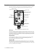
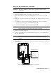
Interconnect Terminal Strip
The interconnect terminal strip is the four-point terminal strip on the lower left side of the
amplifier PCB. Use the interconnect terminal strip to connect the transmitter to a
controller.
Sensor Sockets
There are four sensor sockets located in a circular pattern near the top of the amplifier
PCB. The sensor plugs into these sockets.
Span Pot
The span pot is near the bottom right corner of the amplifier PCB. Use the span pot to
adjust the transmitter’s response output during the calibration procedure.
Zero Pot
The zero pot is above the span pot. Use the zero pot to adjust the transmitter’s target gas-
free output during the start-up and calibration procedures.
CAUTION: There is a third potentiometer on the PCB, the null potentiometer. It is factory-set.
Do not adjust it.
Test Points
The test points (labeled CAL+ and CAL-) are on the right of the interconnect terminal
strip. The test points produce a 100 - 500 mV output that is proportional to the
transmitter’s 4 - 20 mA output. Use the test points and a voltmeter to measure the
transmitter’s output during the start-up and calibration procedures.
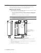
Enclosure
The enclosure enables you to install the CO transmitter at a mounting site that is remote
from the controller. The enclosure also protects the amplifier PCB and wiring connections
made to the transmitter. Use the cable bushing on the bottom of the enclosure to connect
wiring from the amplifier PCB to a controller.
Use the enclosure’s two mounting holes, accessible with the cover removed, to mount the
CO transmitter to a vertical surface at the monitoring site. Use the cover on the front of the
enclosure to access the interior of the enclosure.