
Manual
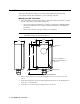

65-2434RK CO Transmitter • 13
Returning to Normal Operation
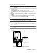
1. Remove the voltmeter leads from the amplifier test points.
2. Secure the cover to the enclosure.
3. When the display reading falls below the alarm setpoints, return the controller to
normal operation.
4. Verify that the controller display reading decreases and stabilizes at 0 ppm CO.
5. Store the components of the calibration kit in a safe and convenient place.
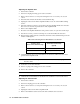
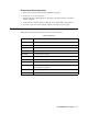
Parts List
Table 6 lists replacement parts and accessories for the CO channel.
Table 3: Parts List
Part Number Description
06-1248RK Sample tubing (order by the foot)
07-0203RK Retaining boot (for filter)
33-7101RK Filter (charcoal)
57-0035RK-01 Amplifier PCB, CO
65-2434RK CO transmitter, complete
71-0061RK 65-2434RK CO Transmitter Manual (this document)
81-0064RK Calibration cylinder (50 PPM CO in air; 34 liter)
81-0076RK-01 Zero air calibration cylinder (34 liter)
81-1050RK Regulator with gauge and knob, 0.5 LPM, for 17 liter and 34 liter
steel calibration cylinders
81-1109RK Calibration cup
ES-1531-CO CO replacement sensor