
Manual

65-2434RK CO Transmitter • 11
6. Remove the charcoal filter from the rubber boot.
7. Place the replacement filter in the rubber boot in the same position as the filter you
removed in the previous step.
8. Reinstall the rubber boot with charcoal filter to the CO sensor.
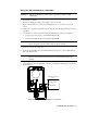
9. Carefully plug the CO sensor with rubber boot and charcoal filter into the socket
pattern on the amplifier PCB.
NOTE: Match the sensor’s male pins with the four female sockets as you plug the sensor
into the sockets.
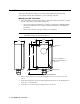
10. Secure the cover to the enclosure.
11. Turn on or plug in power to the controller.
12. Turn on the controller.
Calibration Frequency
Although there is no particular calibration frequency that is correct for all applications, a
calibration frequency of every 3 to 6 months is adequate for most CO transmitter
applications. Unless experience in a particular application dictates otherwise, RKI
Instruments, Inc. recommends a calibration frequency of every 3 months.
If an application is not very demanding, for example detection in a clean, temperature
controlled environment where CO is not normally present and calibration adjustments are
minimal at calibration, then a calibration frequency of every 6 months is adequate.
If an application is very demanding, for example if CO is present often and in significant
concentrations or the environment is not well controlled, then more frequent calibration
than every 3 months may be necessary.
Calibration
This section describes how to calibrate the CO transmitter. It includes procedures to
prepare for calibration, set the zero reading, set the response reading, and return to
normal operation. It describes the test using a calibration kit that includes a calibration
cup, calibration gas, sample tubing, and a fixed flow regulator with an on/off knob. RKI
Instruments, Inc. recommends using a 0.5 LPM (liters per minute) fixed flow regulator.
NOTE: Calibrating the CO transmitter may cause alarms. Be sure to put the controller
into its calibration program or disable external alarms before continuing.
Preparing for Calibration
1. Set a voltmeter to measure in the millivolt (mV) range.
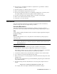
2. Remove the enclosure cover, then plug the voltmeter leads into the test points on the
amplifier PCB.
Plug the positive lead into the test point labeled CAL+; plug the negative lead into the
test point labeled CAL-.