
Instruction Manual

2 • 65-2405RK-04 Combustible Gas Transmitter
Description
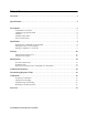
This section describes the components of the combustible gas transmitter. The transmitter
is a 4 - 20 mA type detector head. It consists of the combustible gas detector, calibration
cup/splash guard, amplifier, the amplifier junction box, and the detector junction box.
The two junction box configuration is intended for situations where the detector needs to
be installed at an inaccessible location. The detector junction box can be installed at the
inaccessible location and the amplifier junction box can be installed in a more readily
accessible area.
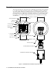
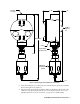
Figure 1: Combustible Gas Transmitter Component Location
Controller Terminal
Strip
Amplifier
LEL PWR / SIG
G
S2 001
S
57-1053RK
BR W
Combustible Gas Detector
Amplifier J-Box
Detector J-Box
Terminal Strip
Jumper Pins,
Factory Use
Only
Factory Adjust
Pot
Factory Adjust Pot
Span Pot
Zero Pot
SPAN
ZERO
Sensor
Current
m A
+ Test Point
- Test Point
Detector Terminal
Strip
Calibration Cup/Splash Guard