
Owner's manual

65-2405RK-03 Combustible Gas Transmitter • 17
Calibration
This section describes how to calibrate the combustible gas transmitter. It includes
procedures to prepare for calibration, set the zero reading, set the response reading, and
return to normal operation.
WARNING: The controller is not an active gas monitoring device during the calibration
procedure.
NOTE: The following procedure assumes the use of a calibration kit which includes a
calibration gas cylinder, a 0.5 LPM fixed flow regulator with an on/off knob, and
a short piece of sample tubing to connect the regulator to the calibration adapter.
Preparing for Calibration
1. Unscrew and remove the amplifier junction box’s cover from the junction box.
2. Set a voltmeter to measure in the millivolt (mV) range.
3. Plug the voltmeter leads into the test points on the amplifier. Plug the positive lead
into the red (+) test point; plug the negative lead into the black (-) test point.
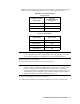
4. Use the following formula to determine the correct test points output for the
calibrating sample.
Output (mV) = (calibrating sample/fullscale) X 400 + 100
For example, with a calibrating sample of 50 %LEL and a fullscale setting of
100 %LEL, the correct output is 300 mV.
300(mV) = (50/100) X 400 +100
5. Place the controller into its calibration mode or disable external alarms.
NOTE: Calibrating the combustible gas transmitter may cause alarms. Be sure to put the
controller into its calibration mode or disable external alarms before continuing.
Setting the Zero Reading
NOTE: If you can verify that the combustible gas transmitter is in a fresh air
environment, you do not need to apply zero air to the detector before adjusting
the zero reading.
1. Screw the regulator into the zero air calibration cylinder.
2. Use the flexible tubing coming from the calibration adapter to connect the regulator to
the calibration adapter.
3. Turn the regulator’s on/off knob counterclockwise to open the regulator.
4. Allow the gas to flow for the length of time determined in “Determining Response
Time” on page 16 and verify a reading of 100 mV (±2 mV). If necessary, use the zero
pot on the amplifier to adjust the reading to 100 mV (±2 mV).
5. Turn the regulator’s on/off knob clockwise to close the regulator.
6. Unscrew the regulator from the zero air calibration cylinder.