
Owner's manual

10 • 65-2405RK-03 Combustible Gas Transmitter
Start Up
This section describes procedures to start up the combustible gas transmitter and place the
transmitter into normal operation.
Introducing Incoming Power
1. Complete the installation procedures described earlier in this manual.
2. Verify that the power wiring to the controller is correct and secure. Refer to the
controller operator’s manual.
3. Turn on power to the controller.
4. Turn on the controller.
5. Verify that the controller is on and operating properly. Refer to the controller
operator’s manual.
NOTE: When first powered up, the transmitter will enter about a one minute period
when the 4-20 mA output is stabilizing and may be above the controller alarm
points or well below zero momentarily. RKI controllers have a one minute
warmup period when the controller does not display any gas reading or give any
alarm indication. The combustible gas transmitter’s 4-20 mA signal should be
stable by the time the controller’s warmup period is over.
CAUTION: Allow the detector to warm up for 5 minutes before you continue with the next
section, “Setting the Zero Signal”.
Setting the Zero Signal
WARNING: Do not remove the junction box cover while the circuits are energized
unless the area is determined to be non-hazardous. Keep the junction box
cover tightly closed during operation.
NOTE: If you can verify that the combustible gas transmitter is in a fresh air
environment, you do not need to apply zero air to the detector before adjusting
the zero reading.
The procedure below describes applying zero emission air, usually called zero air, using a
calibration kit that includes calibration gas, sample tubing, and a fixed flow regulator with
an on/off knob. RKI Instruments, Inc. recommends using a 0.5 LPM (liters per minute)
fixed flow regulator.
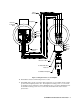
1. Unscrew and remove the amplifier junction box’s cover from the junction box.
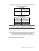
2. Set a voltmeter to measure in the millivolt (mV) range.
3. Plug the voltmeter leads into the test points on the amplifier. Plug the positive lead
into the red (+) test point; plug the negative lead into the black (-) test point.
4. Screw the regulator into the zero air calibration cylinder.
5. Use the flexible tubing coming from the calibration adapter to connect the regulator to
the calibration adapter.