65-2399RK-CH4 Methane Transmitter Operator’s Manual Part Number: 71-0201RK Revision: A Released: 4/12/11 RKI Instruments, Inc. www.rkiinstruments.
WARNING Read and understand this instruction manual before operating transmitter. Improper use of the transmitter could result in bodily harm or death. Periodic calibration and maintenance of the transmitter is essential for proper operation and correct readings. Please calibrate and maintain this transmitter regularly! Frequency of calibration depends upon the type of use you have and the sensor types.
Product Warranty RKI Instruments, Inc. warrants gas alarm equipment sold by us to be free from defects in materials, workmanship, and performance for a period of one year from date of shipment from RKI Instruments, Inc. Any parts found defective within that period will be repaired or replaced, at our option, free of charge.
Table of Contents Overview . . . . . . . . . . . . . . . . . . . . . . . . . . . . . . . . . . . . . . . . . . . . . . . . . . . . . . . . . . . . . . . . . . . 1 Specifications. . . . . . . . . . . . . . . . . . . . . . . . . . . . . . . . . . . . . . . . . . . . . . . . . . . . . . . . . . . . . . . . 1 Description . . . . . . . . . . . . . . . . . . . . . . . . . . . . . . . . . . . . . . . . . . . . . . . . . . . . . . . . . . . . . . . . . . 2 Methane Detector . . . . . . . . . . . . . . . . . . . . .
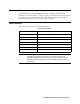
Overview This manual describes the 65-2399RK-CH4 methane transmitter. This manual also describes how to install, start up, configure, maintain, and calibrate the transmitter when it is used with a gas monitoring controller. A parts list at the end of this manual lists replacement parts and accessories for the methane transmitter. Specifications Table 1 lists specifications for the methane transmitter.
Description The 65-2399RK-CH4 transmitter is calibrated to methane. The transmitter utilizes an infrared type of detector which has some advantages over a catalytic type of combustible detector. The infrared detector will generally have a longer service life than a catalytic detector, it will require calibration less often, and it can detect methane even if there is no oxygen in the sample which allows detection of methane in an inert atmosphere.
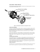
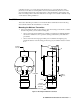
Infrared CH4 %Volume Detector The infrared CH4 %Vol. detector consists of the detector housing body, detector housing cap, cap gasket, and the plug-in sensor. Detector Housing Body Cap Gasket Plug-In IR CH4 %Volume Sensor Detector Housing Cap Hydrophobic Membrane Figure 2: Infrared CH4 %Vol. Detector Component Location Detector Housing Body The detector housing body protects the electronic components within the housing.
Amplifier The amplifier converts the electrical output from the detector to a 4 to 20 mA signal that corresponds to the detection range and transmits the signal to a gas monitoring controller. A foam gasket that orients the amplifier and keeps it from rotating is installed on the bottom of the amplifier. A label on the amplifier indicates the detector drive current. The detector drive current is factory set to 148 mA for the 65-2399RK-CH4.
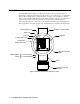
controller. Use the cover on the front of the junction box to access the interior of the junction box. The detector and amplifier are factory installed in the junction box. Three spacers installed on the back of the junction box control the distance of the junction box from a mounting surface and ensure that there is enough room to install a calibration cup on the detector during calibration.
2. At the monitoring site you select, hang or mount the junction box with the detector facing down (see Figure 3). Wiring the Methane Transmitter to a Controller WARNING: Always verify that the power to the controller is off before you make wiring connections. 1. Turn off the controller. 2. Turn off or unplug power to the controller. 3. Remove the junction box cover. 4. The detector leads are factory wired.
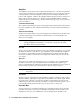
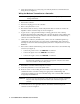
+ 24 VDC 4 - 20 mA In (S) - (DC Ground) Cable sheild Controller Amplifier S S IG/ PWR Green Detector Wires White W G LEL B S PAN ZER O Black R Red J-Box IR CH4 %Volume Detector Figure 4: Wiring the Methane Transmitter to a Controller 12. If shielded cable is used, connect the cable’s drain wire to an available chassis (earth) ground at the controller. RKI controllers typically have a ground stud that can be used to ground the cable’s drain wire.
Start Up This section describes procedures to start up the methane transmitter and place the transmitter into normal operation. Introducing Incoming Power 1. Complete the installation procedures described earlier in this manual. 2. Verify that the power wiring to the controller is correct and secure. Refer to the controller operator’s manual. 3. Turn on power to the controller. 4. Turn on the controller. 5. Verify that the controller is on and operating properly.
voltmeter reading is 100 mV (±2 mV). 11. Turn the regulator’s on/off knob clockwise to close it. 12. Unscrew the calibration cup from the detector. 13. Unscrew the regulator from the zero air calibration cylinder. For convenience, leave the sample tubing connected to the regulator and the calibration cup. 14. Store the components of the calibration kit in a safe and convenient place. 15. Remove the voltmeter leads from the test points. 16. Secure the junction box cover to the junction box.
5. Use the calibration kit sample tubing to connect the regulator to the calibration cup. 6. Set a voltmeter to measure in the millivolt (mV) range. 7. Plug the voltmeter leads into the test points on the amplifier. Plug the positive lead into the red (+) test point; plug the negative lead into the black (-) test point. 8. Use the following formula to determine the correct test points output for the test sample.
Troubleshooting The troubleshooting guide describes symptoms, probable causes, and recommended action for problems you may encounter with the methane transmitter. NOTE: This troubleshooting guide describes transmitter problems only. See the controller operator’s manual for problems you may encounter with the controller. Table 2:Troubleshooting the Methane Transmitter Condition Symptom(s) Probable Causes Recommended Action Fail Condition • Controller indicates a fail condition.
Replacing Components of the Methane Transmitter This section includes a procedure to replace the hydrophobic membrane, a procedure to replace the plug-in IR CH4 %Vol. sensor, a procedure to replace the entire methane detector assembly, and one to replace the amplifier. In most cases, it is not necessary to replace the entire detector assembly. Replacing the Hydrophobic Membrane 1. Turn off the controller. 2. Turn off or unplug incoming power to the controller. 3.
NOTE: When first powered up, the transmitter will enter about a one minute period when the 4-20 mA output is stabilizing and may be above the controller alarm points or well below zero momentarily. RKI controllers have a one minute warmup period when the controller does not display any gas reading or give any alarm indication. The methane transmitter’s 4-20 mA signal should be stable by the time the controller’s warmup period is over.
NOTE: When first powered up, the transmitter will enter about a one minute period when the 4-20 mA output is stabilizing and may be above the controller alarm points or well below zero momentarily. RKI controllers have a one minute warmup period when the controller does not display any gas reading or give any alarm indication. The methane transmitter’s 4-20 mA signal should be stable by the time the controller’s warmup period is over.
Table 5:Reconnecting the CH4 %Vol. Detector to the Amplifier Amplifier Detector Terminal Strip Detector Lead DETECTOR “W” WHT DETECTOR “G” GREEN DETECTOR “B” BLK NOTE: When a transmitter is first powered up with a new amplifier, the initial output may be either high or below zero depending on the setting of the zero pot. Be sure to make arrangements so that this does not cause unwanted alarms. 10. Turn on power to the controller. 11. Turn on the controller and place it into normal operation.
NOTE: The following procedure assumes the use of a calibration kit which includes a calibration gas cylinder, a 0.5 LPM fixed flow regulator with an on/off knob, a calibration cup for the detector, and a short piece of sample tubing to connect the regulator to the calibration cup. Preparing for Calibration 1. Unscrew and remove the junction box cover. 2. Set a voltmeter to measure in the millivolt (mV) range. 3. Plug the voltmeter leads into the test points on the amplifier.
4. Turn the regulator’s on/off knob clockwise to close the regulator. 5. Unscrew the regulator from the calibration cylinder. Returning to Normal Operation 1. Remove the voltmeter leads from the amplifier test points. 2. Unscrew the calibration cup from the detector. NOTE: For convenience, leave the regulator and calibration cup connected by the sample tubing. 3. Secure the junction box cover to the junction box. 4.